CYB306 Cyber-Physical Vehicle System Security
Chapter 8: Human Factors in Transportation Cyber-Physical Systems: A Case Study of a Smart Automated Transport and Retrieval System (SmartATRS)
Objectives
- Introduction
- Related human factors approaches
- Case study
- Discussion
- Conclusions and future work
1. Introduction
Human Factors (HF), also known as ‘ergonomics’, are defined as the scientific discipline concerned with the understanding of interactions amongst humans and other elements of a system.
The rationale behind HF is to understand how a system can be designed so that it is suitable for the intended user by complimenting their abilities, as opposed to users adapting to a design that is challenging.
To achieve this, it is necessary to understand the variability within the user community, including age, cognitive ability, cultural diversity and physical ability.
HF are considered by the UK Ministry of Defense as a systematic systems engineering process known as Human Factors Integration (HFI), which identifies, tracks and resolves human-related considerations, to ensure a balanced development in terms of technologies and human aspects.
This concept can be applied during the development of Transportation Cyber-Physical Systems, together with user-centred design, UX and universal design, to ensure that the system meets expectations.
There are many examples of cyber-physical systems in the transportation sector where the HF approach has been adopted including aircraft flight decks, air traffic control systems and the design of vehicles.
Smart Automated Transport and Retrieval System (SmartATRS) is considered as a Transportation Cyber-Physical System where usability evaluations are conducted to assess the suitability of a system for the user community of people with reduced physical ability.
2. Related human factors approaches
In order to develop SmartATRS, it was necessary to consider aspects of Human Computer Interaction (HCI) in terms of ergonomics of Human System Interaction(HSI), Universal Design and Design for All The ISO standard of ergonomics of HIS was originally recognised as Human-Centred Design (HCD).
It can be defined as an iterative process consisting of five core stages.
The first stage is to understand the context of use in order to generate user requirements.
The requirements are then utilised to produce design solutions that can be evaluated against the user requirements.
The iterative nature of HCD is produced by the involvement of users during the design process, which could lead to modifications to the design of the system.
2.1 Human factors integration
HFI is considered as a system engineering process that allows the human component of a system to be identified and any human-related aspects that would adversely impact the development to be traded off.
The process exists within capability management that concerns the responsibilities of users in capability planning, generation and delivery roles.
It is stated that HFI has multiple benefits including minimising errors in the design through thorough correct analysis of HF, resulting in reduced product recalls, development costs, user training and ongoing maintenance costs.
HFI consists of a framework containing seven domains to ensure that issues, risks, assumptions, constraints and requirements are captured.
These domains are manpower, personnel, training, human factors engineering, system safety, health hazards and social and organizational.
The HFI process can be applied to Transportation Cyber-Physical Systems to provide an evaluation of their integration with the existing processes.
2.2 Human-centred design
One of the key principles of the concept is the involvement of potential users during both the design and development of the system.
Placing the user at the centre of the design in order to achieve the ISO Standard can be accomplished by adhering to the four recommendations stated by Norman.
It is imperative that a system must be easy to evaluate, the users can determine the actions that are possible at any point in time and the structure of a system must be transparent to users including any conceptual models, alternative actions and the outcomes of actions.
Norman’s final recommendation suggests that natural mappings between intentions and required actions should be followed by a system.
Norman also defined seven principles of design that ensures the user is assisted when performing tasks.
These principles include the creation of understandable operating manuals, simplified task structure to avoid memory overloads, planning for user errors to ensure recovery is always possible and ensuring that it is obvious which actions need to be performed to achieve the system goal.
2.3 Usability evaluation
Usability is defined as the quality of a user’s experience when interacting with products or systems that can be measured in terms of effectiveness, efficiency and satisfaction.
A variety of factors can contribute to usability including the ease of learning, memorability, error frequency and intuitive design, which can be evaluated through participative enquiry through the adoption of methods including focus groups, scenarios, surveys and interviews.
An alternative strategy to understand the learnability of a system to new or infrequent users is cognitive walk throughs where a series of tasks are conducted from the user’s perspective.
The System Usability Scale (SUS) and NASA TLX are two tools that can be adopted to assess intuitive design and the demands experienced by users when interacting.
SUS was originally developed by Brooke to provide a ‘quick and dirty’ reliable tool for measuring usability consisting of a 10-item questionnaire with 5 response sections from ‘strongly agree’ to ‘strongly disagree’.
NASA TLX is a subjective workload assessment tool that derives an overall usability score based on the subscales of mental demand, physical demand, temporal demand, performance, effort and frustration and thus determines the effect of each interaction modality on the user.
2.4 Interaction modalities
Traditionally, HCI was considered as unimodal where users can only interact through a single channel, e.g., a keyboard.
However, it is multimodal as users interact with a variety of devices such as the keyboard, mouse and display to perform tasks.
Multimodal systems was originally defined by Oviatt as systems ‘that process two or more combined user input modes in a coordinated manner with multimedia outputs’.
The rationale behind multimodality is to offer alternative channels for users to align with the natural method of interaction in the world (i.e., through the five major senses of sight, hearing, touch, smell and taste).
Advances in hardware and software are enabling multimodal systems to emerge where humans are able to interact through natural methods including speech, touch and gesture.
The advent of smartphones illustrates multimodal interaction where the device can be operated via a variety of methods.
3. Case study
SmartATRS can be considered as a Transportation Cyber-Physical System as it enables a user to transport their powered wheelchair in a vehicle.
Furthermore, the system comprises of multiple independently operable constituent systems (e.g., the automated tailgate, platform lift and motorised driver’s seat, as seen in Fig. 8.1) that can only provide the functionality of SmartATRS when combined together as a cyberphysical system.
SmartATRS was developed to control an existing assistive technology called the ATRS, originally developed by Freedom Sciences Inc.
ATRS is a technically advanced system first featured in New Scientist magazine with the objective of creating a reliable, robust means for a wheelchair user to autonomously dock a powerchair onto a platform lift without the need of an assistant.
ATRS requires a standard multipurpose vehicle to be installed with three components; a motorized seat that rotates and exits the vehicle through the driver’s door, an automated tailgate and a platform lift fitted in the rear of the vehicle.
Using a joystick attached to the driver’s seat, a user with reduced physical ability manoeuvres the powerchair to the rear of the vehicle until it is adjacent to the lift and within line of sight of two highly reflective fiducials.
On an input from the user (via a button press), a laser guidance system comprising a compact Light Detection and Ranging (LiDAR) unit coupled with robotics fitted to powerchair, locates the exact position of the lift and proceeds to autonomously drive the powerchair onto the platform, as shown in Fig. 8.1.
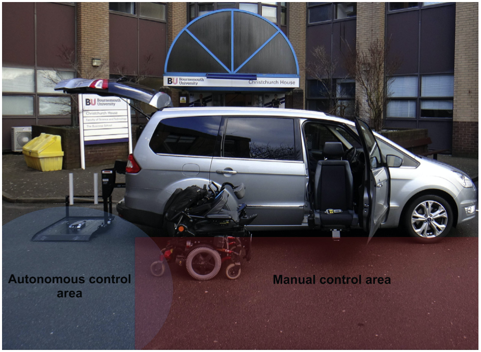
Figure 8.1 ATRS operating zones.
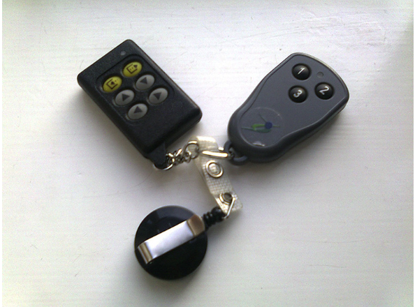
Figure 8.2 Wireless keyfobs used to control ATRS.
3.1 Requirements
- SmartATRS was developed to provide the exact functionality of the keyfobs on a smartphone interface.
- Demonstrations of ATRS to users with reduced physical abilities were performed at the 2011 Mobility Roadshow, a UK consumer-based event, showcasing mobility products and innovation.
- Based on the demonstrations at the Mobility Roadshow, requirements were defined for SmartATRS using Volere Requirements Shells and categorised in terms of Functionality (FR), Interoperability (IR), Maintainability (MR), Performance (PR), Portability (PTR), Reliability (RR), Safety (SFR) and Usability (UR). The defined requirements were as follows:
- (SFR1) SmartATRS shall not prevent ATRS from being operated by the handheld pendants or keyfobs.
- (FR1) SmartATRS shall be able to control the following functions: the Freedom Seat, Tracker Lift and Automated Tailgate.
- (SFR2) SmartATRS shall ensure safe operation of all ATRS functions.
- (UR1) The user interface of SmartATRS shall be created in a design that a user with reduced finger dexterity would be able to use.
- (RR1) SmartATRS shall be reliable, as a user would depend on the system for their independence.
- (FR2) ATRS shall still function as if being operated by the handheld pendants and keyfobs.
- (PR1) SmartATRS shall minimise any additional delay to the functioning of ATRS.
- (MR1) SmartATRS shall be easy to configure by installers.
- (MR2) SmartATRS shall be easy to install into a standard ATRS.
- (PTR1) SmartATRS shall be compatible with all popular smartphone operating systems that have web browsers and customisable voice control.
3.2 System architecture
- SmartATRS was originally developed with two interaction methods (touch and joystick), but this was subsequently increased through the incorporation of head and smartglass-based interaction modalities.
- Fig. 8.3 shows the system architecture diagram for SmartATRS including the integrated existing ATRS components, as well as the component and user interactions.
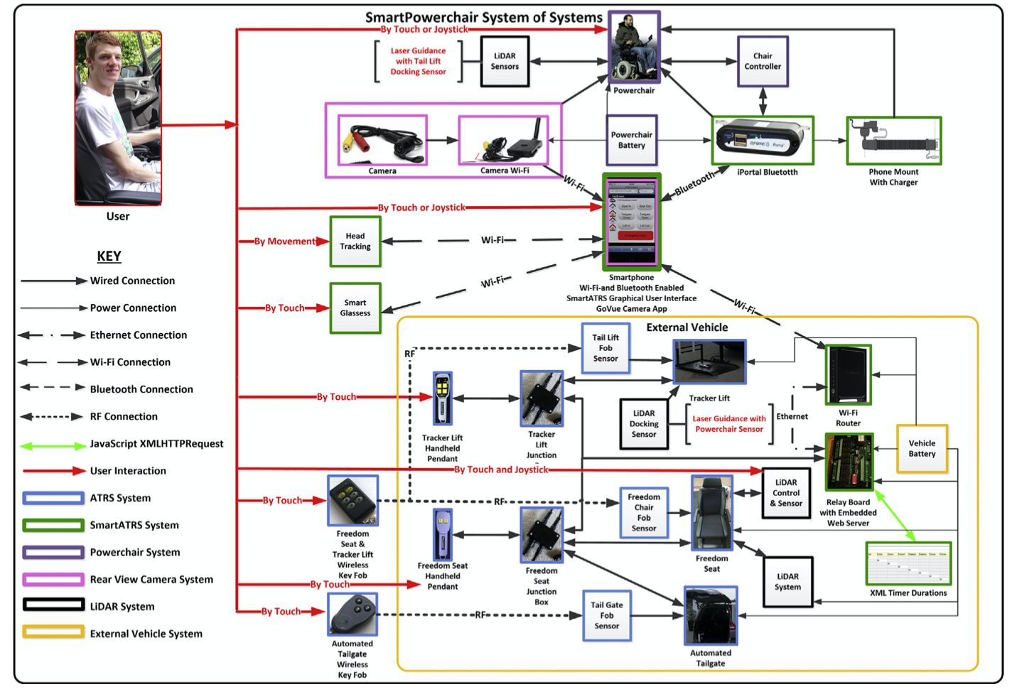
Figure 8.3 SmartATRS system architecture diagram. Component interactions indicated by black and yellow lines (light grey lines in print versions) and the user interactions illustrated in red (dark grey in print versions).
- In the standard ATRS, keyfobs and handheld pendants were the only interaction methods, whereas with SmartATRS, the original interaction methods are touch or joystick based.
- Junction boxes were manufactured to retain the operation of the existing handheld pendants as a backup method.
- As all of the ATRS components contained relays, a relay board comprising an embedded web server was used to interface between the components and JavaScript.
- The server stored the HTML and JavaScript Graphical User Interfaces (GUI) as web pages and JavaScript XMLHttp Requests (objects that transfer data between a web browser and server were transmitted to access an Extensible Markup Language (XML) file).
- The file contains the timer durations for each ATRS function denoted as integers that represented the number of milliseconds that each function was switched on for.
- An XML editor was used to view and change the timer durations, therefore ensuring that the process was not visible to end users.
3.3 User interface design
- The SmartATRS user interface (shown in Fig. 8.4) was developed based upon the views of users at the 2011 Mobility Roadshow and incorporated user feedback and safety features that were not present in the keyfobs.
- Seven command buttons were used to activate each ATRS function.
- The red emergency stop button was twice the width of the other buttons, so that it could be selected quickly in an emergency situation.
- The large buttons reduced the risk of incorrect selection by users with reduced finger dexterity.
- The command button changed colour depending on the current state of SmartATRS, with blue representing currently operating features and orange to represent a disabled function.
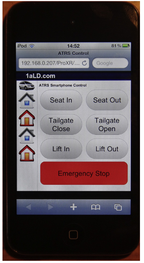
Figure 8.4 SmartATRS user interface.
3.4 Risk analysis
- As identified in the fifth systems safety domain of the HFI process, it is important to consider risks in order to achieve a user-centred design.
- Transportation Cyber-Physical Systems can present multiple risks to users due to motorised physical components.
- Therefore, the SmartATRS case study was used to establish potential risks that can exist with Transportation Cyber-Physical Systems technologies in a three-stage risk analysis framework for System of Systems (SoS), consisting of threat identification, risk analysis and risk evaluation.
- In order to identify risks, an in-depth understanding of the system’s structure needs to be established in terms of threat sources and vulnerable system elements.
- This results in identification of risks that are present within the system environment.
Table 8.1 Likelihood and Impacts of SmartATRS Risks
| ID | Identified Risk | Likelihood (L, M, H) | Impact on Systems | Impact on Interoperability | Impact Level (L, M, H) | Risk Level (L, M, H) |
|---|---|---|---|---|---|---|
| S1 | Smartphone must be in range of the router for Wi-Fi to be accessible. | L | Wi-Fi connection will not be available for smartphone. The system cannot be used. | The smartphone will not be able to connect and communicate with other systems. | H | M |
| S2 | Vehicle cannot receive commands if the smartphone is not available. | M | The system cannot be operated without the smartphone. | System cannot operate. | H | H |
L, Low; M, Medium; H, High.
3.5 Task analysis, usability, evaluations and workload measurements
- Controlled usability evaluations were performed involving the user community to obtain an accurate assessment of usability of varying modalities.
- Prior to the conduction of the evaluations, it was necessary to perform a Hierarchical Task Analysis (HTA) to obtain an understanding of the tasks involved with operating SmartATRS.
3.5.1 Hierarchical task analysis
- Adopting HTA enabled the tasks to be performed in the controlled usability evaluations to be determined.
- This was achieved by deconstructing the high-level parent task (i.e., departing or arriving in a vehicle) into subtasks by using a numbering system in a hierarchical structure, as shown in the extract in Fig. 8.5.
- The SmartATRS HTA for departing in the vehicle consisted of six subtasks: (1) preparing vehicle, (2) activating lift and seat out of vehicle, (3) preparing powerchair, (4) autonomous docking, (5) activating lift and seat into vehicle and (6) departure.
- These tasks needed to be performed sequentially in order to successfully depart in the vehicle with the powerchair safely stowed.
- The addition of screenshots of SmartATRS to the HTA highlighted the tasks currently supported by smartphone interaction.
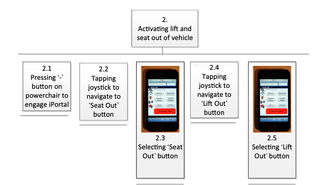
Figure 8.5 An extract of the SmartATRS Hierarchical Task Analysis for departing in a vehicle.
3.5.2 Evaluation 1 (keyfob, touch and joystick based interactions)
- The first controlled usability evaluation was conducted to assess the usability of the interaction methods: keyfobs, touch and joystick.
- The evaluation also provideda means to verify the GUI design of SmartATRS to ensure that it was ‘fit for purpose’.
- The participants of the evaluation (consisting of eight males and four females between the ages of 20 and 60) operated an ATRS-equipped vehicle in an outdoor environment.
- The outdoor aspect of the evaluation inherently produced safety implications for participants who were unfamiliar with operating ATRS.
- In the subsequent evaluations, a simulation was utilised.
- The participants were given a briefing prior to the commencement of the evaluation, consisting of an introduction to ATRS and SmartATRS, the purpose of the evaluation and the expectations of the participants.
- There was an opportunity for questions to be asked.
- The participants performed a series of six tasks using keyfob, touch and joystick based interactions, before completing a questionnaire pack concerning the usability of the methods.
3.5.3 Evaluation 1 results
- SUS: Analysis using the Adjective Rating Scale revealed that keyfob interaction achieved a score of 50.5 (‘Poor Usability’), whereas touch based achieved 81.3 (‘Good Usability’) and interaction using the joystick achieved 63.8 (‘OK Usability’).
- This clearly highlighted that touch interaction was the most usable, with most participants finding keyfob-based interaction challenging.
- One of the most important results highlighted the safety of the emergency stop function and was found when 100% of participants agreed that it was safe using SmartATRS, compared with only 33% using the keyfobs.
- This result was supported by the results from emergency stop times for the keyfobs and touch-based interaction.
- NASA TLX: The box plots in Figs 8.6 and 8.7 provide an example of the comparison of the workload experienced when using keyfob, touch and joystick-based interactions.
- Fig. 8.7 illustrates the differences in the workload experienced between interaction methods and show the minimum, lower-quartile, median, upper-quartile and maximum values.
- It can be seen that touch- based had a significantly lower workload level in all workload types than the keyfobs.
- There are greater mental and physical demands with keyfobs than touch-based interactions.
- As there is an increased likelihood of not successfully accomplishing the tasks with keyfobs, it was found that the temporal demand was higher, whereas with touch-based interactions, there was a low temporal demand as there is an improved chance of accomplishing tasks successfully.
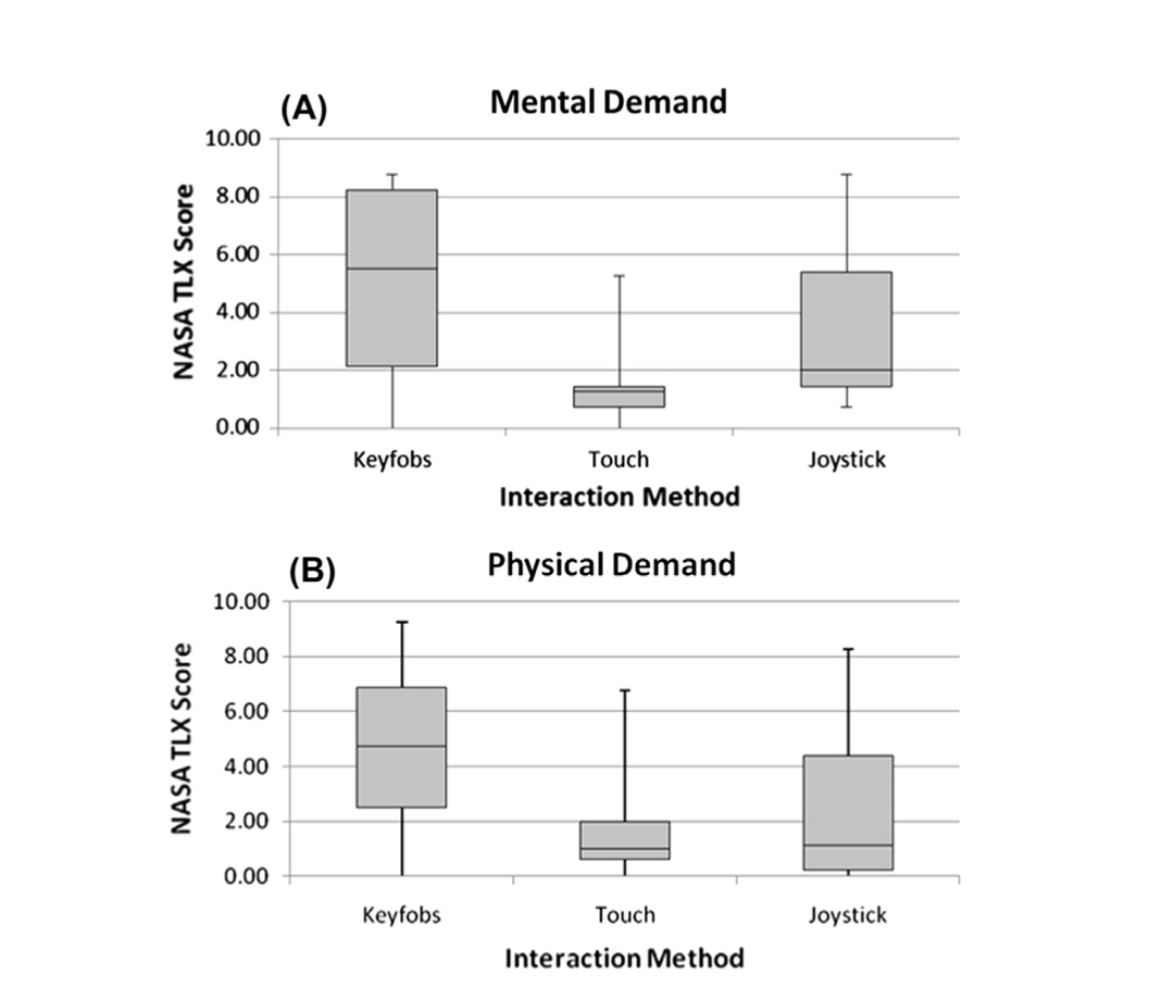
Figure 8.6 Comparing (A) Mental and (B) Physical Demand experienced.
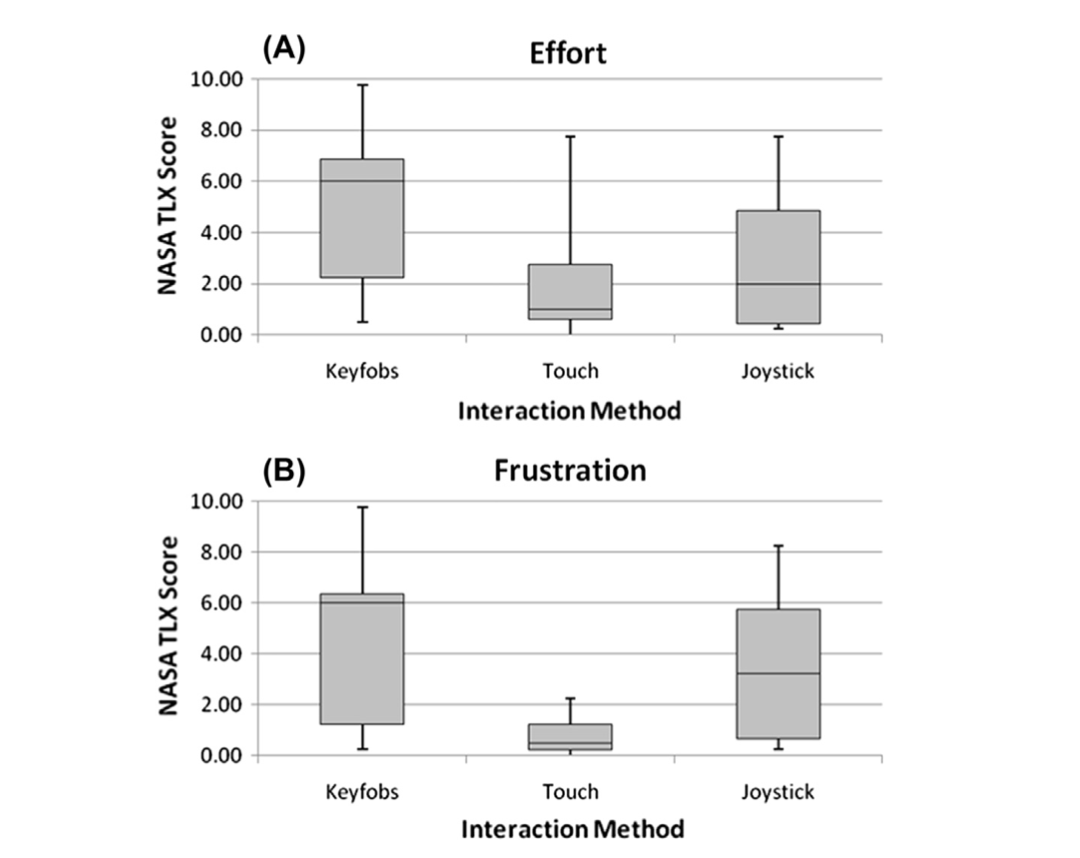
Figure 8.7 Comparing (A) Effort and (B) Frustration experienced.
3.5.4 Evaluation 2 (touch and head based interactions)
- The purpose of the second control usability evaluation was to compare touch and head based interaction modalities through a simulation of SmartATRS.
- These simulations consisted of a relay board with an embedded web server (identical to the relay board located in the vehicle), smartphone, Windows laptop and a projector.
- The web server on the relay board was connected to a wireless LAN module so that a smartphone could connect to the relay board wirelessly.
- The same user interface for SmartATRS existed in the simulation with the relays being operated from the JavaScript, but the relays were not connected to any functions.
- A Windows laptop also connected to the relay board wirelessly and executed JavaScript code that continuously monitored the state on the relays.
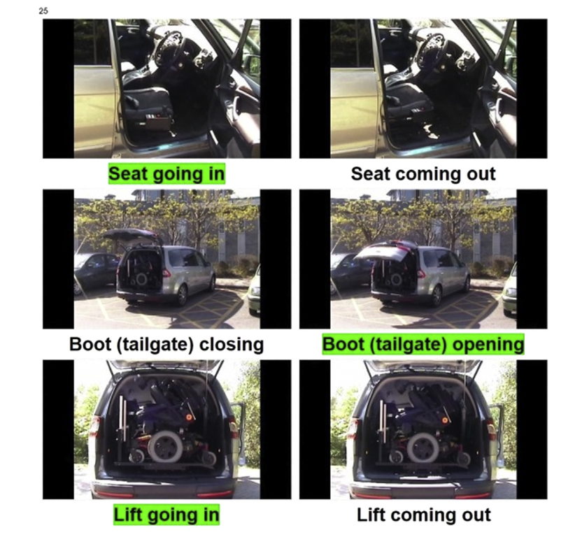
Figure 8.8 SmartATRS simulation interface.
3.5.5 Evaluation 2 results
- SUS: Analysis using the Adjective Rating Scale revealed that touch-based interaction achieved a score of 75.7 (‘Good Usability’), whereas head-based achieved 36.7 (‘Poor Usability’). This clearly highlighted that touch interaction was the most usable, with most participants finding interaction with the head challenging.
- A second important result identified the safety of the emergency stop function with each interaction method.
- The results revealed a standard deviation of 4 s for the fingers compared to 14 s for head tracking.
- The average stopping times were 4 and 16 s, respectively.
- The dramatically increased stop times for head tracking were observed to be the time taken to navigate to the emergency stop button using switch control, indicating that using the head is more unpredictable than fingers.
- NASA TLX: The box plot comparisons in Fig. 8.9 illustrate the differences in the workload experienced between touch and head-based interaction.
- From the minimum, lower-quartile, median, upper-quartile and maximum values, it is evident that ‘fingers’ showed lower mental and temporal demands, thus proving that head tracking was more mentally demanding and stressful to complete efficiently.
- A second important observation was the considerably higher physical demand for head tracking resulting in 65% of participants either not being able to sufficiently use switch control at all or finding it extremely challenging.
- The remaining 35% of participants experienced low workload levels when using the head due to having full range of neck movement.
- The limitations of head tracking are also reflected by the increased effort and frustration levels compared to ‘fingers’.
- Overall the box plots were fairly conclusive that in this particular instance, touch-based interaction was more effective than head interaction.
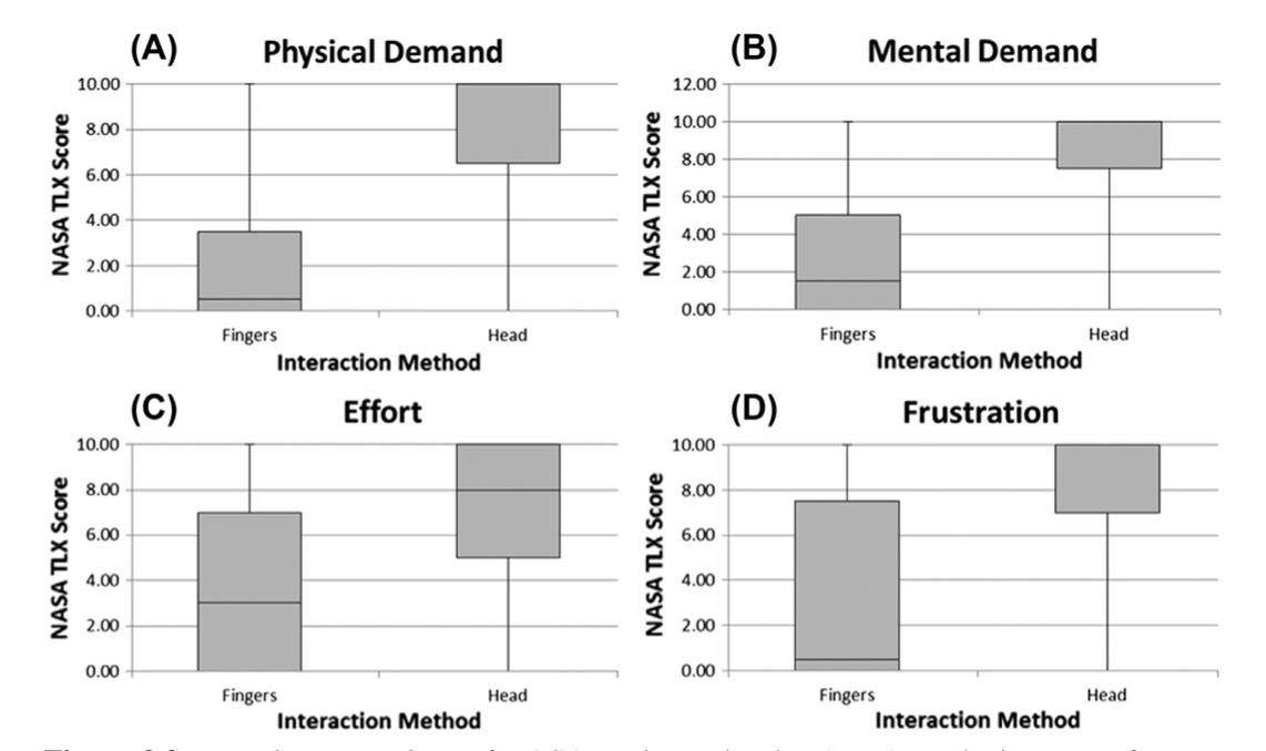
Figure 8.9 Box plot comparison of NASA Task Load Index (TLX) results in terms of (A) Physical Demand, (B) Mental Demand, (C) Effort and (D) Frustration.
3.5.6 Evaluation 3 (touch and smartglass based interaction)
- The third evaluation compared touch-based and smartglass interaction mediums to ascertain whether smartglasses could potentially be useful for people with reduced physical ability.
- The evaluation was conducted using the Recon Jet smartglass with participants at the 2016 Mobility Roadshow.
- The simulation of SmartATRS, used for Evaluation 2, was applied to this evaluation to eliminate the use of a vehicle and the ATRS components.
- It was necessary to develop a separate SmartATRS user interface for the Recon Jet due to the small display size, as shown in Fig. 8.10.
- The interface retained an identical layout as the smartphone interface, but the buttons were reduced in size so that all could be viewed on the single screen.
- To enable navigation using the touchpad on the Recon Jet, additional JavaScript code was developed that converted the American Standard Code for Information Interchange (ASCII) codes produced from the touchpad into onfocus events.
- Due to the poor usability of the Recon Jet previously established during a feasibility trial, it was therefore decided not to conduct a controlled usability evaluation; therefore no statistical results were obtained.
- The participants for the evaluation had varying physical conditions (including cerebral palsy, spina bifida, arthritis and poliomyelitis) resulting in the use of manual or powered wheelchairs.
- The Recon Jet was integrated into the SmartATRS network in order for the user interface to be displayed and participants were invited to wear the smartglass to ascertain whether they could read the display.
- If it was readable, the participants were instructed on the operation of the smartglass touchpad and buttons, as well as the functionality of the simulation.
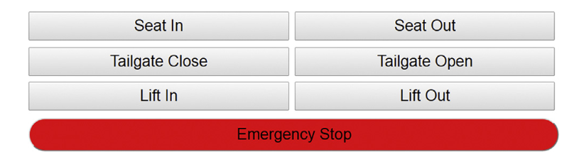
Figure 8.10 SmartATRS user interface for Recon Jet.
3.5.7 Evaluation 3 results
- The majority of the user group experienced challenges to position the smartglass on their heads due to insufficient dexterity.
- Further challenges were caused by the small text on the user interface resulting in the button names being unreadable and participants were consequently unable to conduct the evaluation.
- A further difficulty for most participants was the small buttons on the device that required significant dexterity to operate.
- The overall result of the evaluation was that the Recon Jet was unsuitable for use as an alternative modality for SmartATRS.
Discussion
- The case study focused on SmartATRS that controls ATRS. This is an example of a Transportation Cyber-Physical System that consists of constituent systems that interact in order to transport a powerchair in a vehicle.
- SmartATRS was developed to provide an alternative modality of interaction for ATRS to replace the existing keyfobs, which were challenging for people with reduced finger dexterity to operate.
- The system was centred around a relay board with an embedded web server that interfaced with the ATRS functions.
- This produced a solution that was smartphone independent due to the user interface being accessible from any Wi-Fieenabled device.
- The importance of safety in cyber-physical systems was the rationale behind the development of a risk analysis framework for SoS.
- The framework considered at the three key elements of risk being HSI, interoperability analysis and emergent behaviour.
- The usability of the modalities of interaction for SmartATRS was measured through the conduction of controlled usability evaluations that compared keyfob, touch, head and smartglass based interaction.
Conclusions and future work
- The knowledge obtained through the development of SmartATRS can be used to generate future directions for Transportation Cyber-Physical Systems.
- The integration of technologies to provide different interaction modalities could improve the usability and user-centred design for people with reduced physical ability.
- Alternative interaction modalities that could be investigated include air gesture, electroencephalogram, head and eye tracking.
- These would provide methods of interaction for users who do not possess the required dexterity to interact through traditional touch-based mediums.
- SmartATRS is presented as a cyber-physical system that provides transportation of a powerchair in a vehicle and consists of a number of constituent systems including the original ATRS components of a motorised driver seat, automated tailgate, platform lift and a LiDAR unit that provides the autonomous docking of the powerchair.
- To assess the usability of SmartATRS to align with HCD, three control usability evaluations were conducted to compare the interaction modalities of keyfobs, touch, joystick, head and smartglasses.
- Future evaluations are planned to assess the possibilities of other technologies being integrated into the SmartATRS cyber-physical system.
- It will be essential to determine whether the technologies retain the safety and existing functionality of the system to enable transportation of a powerchair in a vehicle.