Concept of Using the MBSE Approach to Integrate Security Patterns in Safety-Related Projects for the Automotive Industry
Piotr Piatek , Piotr Mydłowski, Aleksander Buczacki , and Szczepan Moskwa
Abstract— The automotive industry is undergoing significant changes due to increased connectivity, data usage, and vehicle autonomy, which pose new challenges and increase the attack surface of vehicles. To effectively address these challenges, all design tasks in automotive projects need to be well-coordinated and prioritize vehicle security. Model-Based Systems Engineering (MBSE) provides a comprehensive approach that allows multiple engineering disciplines to work concurrently. In this study, we propose the integration of well-established security solutions, such as Security Patterns, into safety-critical automotive systems using the MBSE approach. Our work presents a procedural flow for incorporating Security Patterns into the system model, emphasizing the inclusion of cybersecurity (CySe) and functional safety (FS) actions. To meet the regulatory requirements, we selected the IDS (Intrusion Detection System) pattern as a key component of our proposed CyberSafety Design Framework. In a real-world case study of an Advanced Emergency Braking System (AEBS), we evaluated the effectiveness of our framework by integrating the IDS pattern with TARA and HARA assessments. Our results demonstrate the feasibility of merging design processes within an MBSE framework, reducing design effort and aligning with the security by design principle. Future research should explore the application of different Security Patterns in conjunction with SOTIF systems, and industry efforts should be directed towards standardizing the collaboration between cybersecurity and safety.
Index Terms— Model-based systems engineering (MBSE), cybersecurity (CySe), functional safety (FS) security pattern (SP), automotive.
I. INTRODUCTION
THE increasing connectivity and complexity of automotive systems, driven by the rise of autonomous and electric vehicles, present new challenges in ensuring both safety and security. The prevailing vehicle architectures rely on the CAN protocol, with numerous successful attacks exploiting vulnerabilities inherent in this dated architecture [1]. Future vehicle platforms are steering towards Ethernet-based architectures.
Manuscript received 9 May 2022; revised 19 August 2023 and 1 May 2024; accepted 28 July 2024. Date of publication 30 August 2024; date of current version 1 November 2024. This work was supported by the Faculty of Electrical Engineering, Automatics, Computer Science and Biomedical Engineering, AGH University of Krakow. The Associate Editor for this article was E. Kaisar. (Corresponding author: Piotr Pi ˛atek.)
Piotr Pi ˛atek, Piotr Mydłowski, and Szczepan Moskwa are with the Faculty of Electrical Engineering, Automatics, Computer Science and Biomedical Engineering, AGH University of Krakow, 30-059 Kraków, Poland (e-mail: piatek@agh.edu.pl).
Aleksander Buczacki is with the Faculty of Mechanical and Industrial Engineering, Warsaw University of Technology, 02-524 Warsaw, Poland.
Digital Object Identifier 10.1109/TITS.2024.3444048 to mitigate these vulnerabilities, leveraging Security Patterns as solutions for known weaknesses. However, the adoption of Ethernet introduces its own set of challenges, warranting cautious consideration due to the potential for introducing additional vulnerabilities.
Risk analysis is an indispensable aspect of modern system design. It serves as the cornerstone, providing the basis and justification for architectural decisions, while also demonstrating a systematic engineering approach to design.
Traditionally, safety (FS) and security (CySe) have been addressed as separate disciplines in the automotive industry, with dedicated processes and guidelines respectively according to ISO 26262 [2] and ISO 21434 [3]. However, there is a growing recognition that integrating FS and CySe is crucial to achieve comprehensive protection against potential risks and threats [4].
The Electronic Control Unit (ECU) design and development process involved many engineering competences, e.g., software developers, electric, electronics, mechanical, industrial engineers, and business competences, e.g., procurement, logistics, project management, production, finance. Due to this companies are looking for the possibilities of how to increase effectiveness and better coordination and communication within the ECU design and development process. The model-based systems engineering (MBSE) approach is one considered, which may support engineering competences in design and development activities of ECU [5]. MBSE enhances ECU design and development by facilitating seamless collaboration, accelerating change management processes, streamlining testing, improving system understanding, and promoting better decision-making to address industry demands for efficiency, speed to market, and collaborative innovation.
Duan and Hongjun introduced systemic hazards analysis approach based on MBSE verified on the Automatic Emergency Braking System (AEBS) design [6] and Sirgabsou et al. recommended model-driven proposal to ensure automotive embedded software safety [7]. Luo et al. proposed a framework for CySe requirements management dedicated to automotive [8]. Japs focused on the utilization of the MBSE approach to support the cybersecurity concept development [9]. Haring presented utilization of SysML diagrams for the safety and cybersecurity assessment automation [10]. Amorim proposed the systematic pattern approach for safety and security coengineering based on the traditional systems engineering process [11].
Examples of the use of security patterns for automotive systems can be found in the current literature [12], [13]. There are also a few examples of employing the MBSE approach for automotive system safety and security assessment [14]. However, there is still a gap in the application of the MBSE to the use of security patterns in automotive system design.
In this paper, we propose a novel system analysis and design framework that aims to bridge the gap between MBSE, FS, and CySe in automotive systems. The framework provides a procedural flow for incorporating Security Patterns into the system model, where CySe and FS actions are included in a unified approach. Our objective was to establish a systematic method that addresses the potential conflicts, aligns redundant controls, and enables efficient management of FS and CySe processes. Fundamentally, it results in the formulation of shared design goals, which improves system architecture quality and lowers the likelihood of risk.
The key contribution of our work lies in the development of the CyberSafety Design Concept, which integrates the Hazard Analysis and Risk Assessment (HARA) and Threat Analysis and Risk Assessment (TARA) processes. By bringing these processes together, we aim to streamline the identification and mitigation of potential risks, considering both safety and security aspects, as well as to increase efficiency of the ECU design process. Furthermore, we utilize Security Patterns to provide concrete security control recommendations that can be implemented in the system model, which follows the MBSE paradigm. We conclude with definition of design goals used for architecture refinement.
To evaluate the effectiveness of our proposed framework, we present a case study focusing on an Advanced Emergency Braking System (AEBS). We perform HARA and TARA analyses on the AEBS system and demonstrate the interconnections between FS and CySe considerations. While the case study’s initial focus is on the application of an Intrusion Detection System (IDS) as a security control, which is mandatory by means market regulations, we emphasize that the framework is applicable to a broader range of vehicle subsystems. IDS is a primary feature of the CySe system and may focus also on the analysis of physical parameters (e.g., frequency and voltage) [15] or digital information [16], [17].
To validate our approach, we discuss the verification process and present the results obtained from our analysis. Additionally, we highlight the importance of considering the impact of security controls on safety and how they contribute to achieving the desired safety and security goals. By addressing potential conflicts, aligning redundant controls, and providing a comprehensive framework, our work aims to improve the overall safety and security of automotive systems.
In Section II, we introduce the base concepts used in our research. Section III presents the CyberSafety Framework, outlining the procedural flow for integrating safety and security measures. In Section IV, we apply the framework to a real-world case study of an AEBS system. Section V discusses the outcomes of the case study and explores the broader implications of our findings. Finally, in Section VI, we provide concluding remarks and emphasize the significance of integrating safety and security in the automotive industry.
II. MAIN ELEMENTS OF SYSTEM DESIGN
In this section, we present the design consideration, which shall be included during system design process, approach to product development based on the elements of Functional Safety and Cybersecurity standards [2], [3]. We establish direct links between the Work Products (WP), ensuring transparency and demonstrating the cause-and-effect relationship. The proposed safety model serves as a foundation for future discussions on the application of MBSE in conducting analyses and gaining a holistic view of safety throughout product development. Our focus in this article is on concept creation and system design and development. Aligning CySe and FS standards faces challenges in strategy, analysis, and requirements from a cybersecurity perspective, primarily due to maturity gaps between the standards, varying levels of industry implementation, differing risk assessment approaches, terminology, and expected work products. Bridging these gaps necessitates comprehensive tools covering safety and security, establishment of common analysis and requirements, and careful consideration of strategy to create a cohesive framework addressing both safety and security concerns in automotive systems.
A. Analyses in the Context of Functional Safety
ISO 26262, derived from IEC 61508 [18], focuses on ensuring the functional safety of electrical/electronic (E/E) systems in on-road vehicles by assessing potential hazards caused by malfunctions. It utilizes the V-model as a reference process model, emphasizing traceability and early-stage focus in product development. The standard is crucial for E/E systems at the vehicle level, defining functions that require electrical and/or electronic systems to operate safely The development process includes item definition, Hazard Analysis and Risk Assessment (HARA), and a Functional Safety Concept (FSC), with HARA identifying hazardous scenarios and determining risk classifications, while FSC describes safety goals and methods for fault tolerance [19], [20], [21], [22], [23].
B. Analysis in the Context of Cybersecurity
ISO 21434, introduced in August 2021, addresses the need for cybersecurity standardization in the automotive industry by providing guidelines for cybersecurity risk management across various stages of E/E system development. It follows a V-Model approach and emphasizes activities such as Item Definition, TARA analysis, and setting Cybersecurity goals in the Concept Phase. TARA, or Threat Analysis and Risk Assessment, is a critical process in ISO 21434, focusing on identifying threats, assessing associated risks, and determining risk mitigation actions. It involves analysing asset protection, damage scenarios, threat and attack vectors, and ultimately deciding on risk treatment measures to control identified risks [25].
C. Security Patterns
With increasing attention on security, it’s evident that robust security measures are essential across all business sectors, including automotive [26].
Key issues in integrating security into projects include overlooking security in initial design, recurring breaches due to known vulnerabilities, and insufficient security expertise among project participants [27].
Basic security issues in business often have established solutions, highlighting the importance of recognizing patterns. System architecture patterns offer proven solutions to recurring design challenges, consisting of interconnected roles and methods for constructing various design structures [9], [26].
Design Pattern follows the format below, as stated by [28]:
- Name – name a summary of the pattern.
- Also Known as – other names of the pattern.
- Example – a real-life example of a design problem and why a pattern solution is required.
- Context – situations where the pattern may be applied.
- Problem - the issue that the pattern attempts to solve.
- Solution - the pattern’s underlying essential solution principle.
- Structure - a thorough description of the pattern’s structural features.
- Dynamics - common scenarios describing the pattern’s run-time behaviour.
- Implementation - instructions for putting the pattern into action.
- Example Resolved - any crucial components for resolving the example should be discussed.
- Variants - a quick summary of a pattern’s variants or specialisations.
- Known Uses - Taken from existing systems, examples of how to use the pattern.
- Consequences - the pattern’s advantages and disadvantages, as well as any liabilities.
The field of security pattern research has been going on for 20 years now [29], [30], [31]. Higher-level security mechanisms were captured and organised into abstract patterns, which drove cross-application security patterns [32], [33]. This covers software systems, business systems, etc. The security pattern applies to all aspects of the development process, beginning with requirement elicitation and continuing through system design, development, and testing [34], [35].
Standard IT security solutions are not the same as automotive security solutions. Performance constraints, invehicle E/E design, communication mechanisms, and safetycritical requirements all play a significant role. The cybersecurity approach in automotive embedded systems prioritizes establishing robust hardware security roots of trust and efficient cryptographic engines to combat cyber threats and safeguard sensitive automotive systems. Unlike standard IT environments, the automotive industry places greater emphasis on real-time responsiveness, safety-critical functionality, and stringent timing requirements to ensure vehicle safety and regulatory compliance. This necessitates thorough testing, adherence to strict development protocols, and meticulous consideration of safety implications throughout the lifecycle of automotive electronics, reflecting a higher level of scrutiny and precision compared to standard IT solutions. The [9] recommended the following Automobile Security Pattern Template to meet the needs of the automotive industry:
- Pattern Name - a pattern’s name and classification
- Intent - what security concern is addressed by the pattern and how it can be used
- Motivation - a brief history of the security issue, as well as a procedure for resolving it
- Properties - the features of STRIDE1 that are addressed by this pattern
- Applicability - the recommended solution type
- Structure – UML2 diagram of the pattern’s structure
- Behaviour – UML dynamic diagrams of the pattern
- Constraints - specifies the constraints that have been imposed on the pattern’s implementation.
- Consequences - discuss the pattern’s impact on the CIA3 triad
- Known Uses - examines examples of this pattern’s application in automotive situations
- Related Patterns - any security or design patterns that are related to the supplied pattern
At the same time, [9] introduces the security patterns for the automotive sector. Table I.
The list of security patterns for the automobile industry provided is not entirely complete. More research in this area is desperately needed. For the purposes of this study, we will employ the Signature IDS (Intrusion Detection System) pattern as a security control that can be used to detect malicious behaviour in the developed system.
Security patterns are central to MBSE since they provide proven solutions to system security issues, in line with MBSE’s emphasis on using models to manage complex systems throughout their lifecycle. Incorporating security patterns into MBSE enhances the engineering process by facilitating abstraction and visualisation, promoting reuse and consistency, enabling early identification of security needs, and facilitating traceability and impact analysis.
TABLE I PATTERNS FOR THE AUTOMOTIVE SECTOR [9]
| Security Pattern | Short Description |
|---|---|
| Authorization | Structure for access control to resources. |
| BlackList | Blocking the malicious traffic. |
| DDoS Redundancy | Adding a redundancy in case of Distributed Denial of Service attack. |
| Firewall | Introduces a structure for network traffic filtering. |
| Multifactor Authentication | Additional authentication of communication actor. |
| Multilevel Security | Managing an access level in a designed system. |
| Signature IDS | Provides a mechanism for anomaly detection. |
| Symmetric Encryption | Encryptions on communication traffic. |
| Tamper Resistance | Introducing the strategy of preventing an unauthorized change in the system. |
| Third Party Validator | Validation of messages broadcasted in each network. |
D. Model Based Systems Engineering
The MBSE approach for systems engineering assumes that all information on the designed system is stored in one repository (one model) [36]. While MBSE has gained popularity [37], FS and CySe analyses are often conducted separately, due to their historical development, differing focuses, and distinct methodologies: FS analysis, established since 2011, ensures safe operation of vehicle functions, while CySe analysis, introduced later, protects against malicious attacks. This separation, while addressing specific aspects of system integrity, may overlook potential interactions between safety requirements and cybersecurity measures, potentially leaving vehicles vulnerable to complex cyber-physical threats. Proposed approach allows for achieving design analyses from different perspectives. The MBSE approach also changes from the documented related, often disintegrated engineering to integrated digitally. Fully model based approach is still not possible due to the complexity and interdisciplinarity of the designed system. Still, many separated or not fully connected sub-models are used.
The adoption MBSE faces challenges related to human and technological factors, such as awareness, resistance to change, and resource availability. Executive sponsorship and upfront investment are crucial for addressing these challenges early on, while strategies and tools need to address complexity management from the outset. Challenges in cybersecurity and functional safety integration include tool integration, process adaptation, and ensuring error-free transitions between models, particularly in the automotive and IoT domains.
Apart from already mentioned factors, the automotive sector faces challenges in implementing MBSE due to considerations and challenges arising from real-time requirements. These include ensuring real-time responsiveness of systems, managing data transfer and processing speed, and coordinating complex interactions between different components within the vehicle architecture. In addition, the integration of real-time requirements highlights the need for improved development practices and cybersecurity measures to meet the demands of an increasingly connected automotive environment. The lack of standardized approaches, coupled with organizational dependencies and product-specific considerations, further complicates MBSE implementation [54].
The novelty of our presented solution lies in the integration of FS and CySe analyses into the MBSE approach for embedded systems design and development in the automotive industry. Our approach aims to bridge this gap by incorporating FS and CySe considerations within the system model, facilitating better understanding, communication [38], and collaboration between teams. This integrated approach addresses the growing need for holistic system design that encompasses both safety and security aspects, enhancing the overall resilience and protection of automotive systems.
III. CYBER SAFETY DESIGN FRAMEWORK
In this section, we unveil our proposed framework for harmonizing safety and cybersecurity in automotive systems. The concept underscores the essential need for a seamless constructive collaboration between FS and CySe activities fostering a refined System Model. These intertwined activities mutually complement and reinforce one another.
The System Model stands as a cornerstone, encapsulating System Architecture and Stakeholder-derived System Requirements. It ensures that FS and CySe considerations are integrated from the initial stages of development and run on the same defined Item. By establishing this comprehensive System Model, design and development teams are empowered to grasp the intricate interplay between FS and CySe.
To further enhance the integration of FS and CySe, the framework emphasizes the importance of interactions during the (HARA TARA) phases. These interactions facilitate the identification of potential threats and risks, ensuring that the system model adequately addresses both safety and cybersecurity concerns. This integrated approach ensures that safety considerations are embedded throughout the system development process in accordance with ISO 26262 principles.
Key aspect of the proposed framework is the alignment of safety and security goals, which complements the CyberSafety Goals. At the same time by applying Security Patterns, Security Goals can be realized, and System Model can be refined. These patterns amplify Security Goals and enriches the System Model. By strategically aligning Security Patterns with overarching goals, our framework catalyses the selection and application of optimal security solutions. This integrative feat is graphically depicted in the CyberSafety Analysis Metamodel, enriched by Security Patterns, all orchestrated within the realms of Model-Based Systems Engineering (MBSE) methodology. Fig. 1.
To depict the interdependencies within the CyberSafety Metamodel, our approach is further enriched through the integration of additional Model-Based Systems Engineering (MBSE) diagrams. These diagrams meticulously outline the delineation of ports and interfaces interlinking various processes, augmented by a comprehensive detailing of Flow Properties, what is shown in Fig. 2.
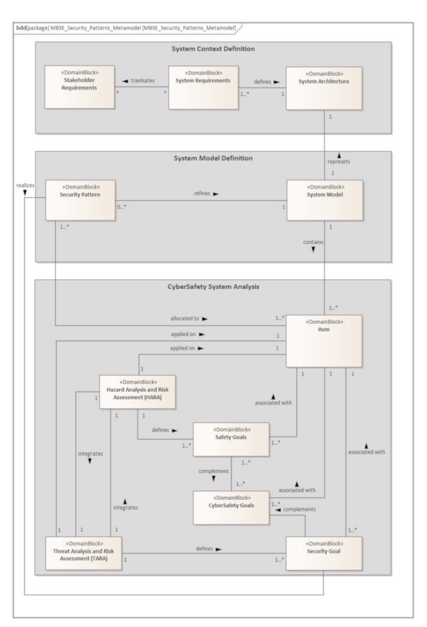
Fig. 1. CyberSafety analysis metamodel with Security Patterns based on MBSE approach.
This multifaceted integration, represented through the intricate web of ports and interfaces, crystallizes the symbiotic relationship between safety, cybersecurity, and system architecture. The strategic introduction of Security Patterns amplifies this constructive interaction, fortifying the overall system’s robustness while catalysing the evolution of requirements, components, and policies. This dynamic integration vividly underscores the pivotal role of SP in orchestrating a harmonized and fortified automotive system development. Introducing a joint CyberSafety design framework in automotive systems presents both risks and opportunities. Challenges include human and technological factors such as awareness, change resistance, and resource availability. However, executive sponsorship and upfront investment can mitigate these challenges. The integration of cybersecurity and functional safety (FS) requires alignment in design, processes, and requirements/architecture, promoting complementary steps and reducing conflicts. Collaboration between disciplines like cybersecurity and FS is crucial, demanding a structured approach, defined roles, and continuous monitoring, what our approach provides.
IV. CYBERSAFETY DESIGN FRAMEWORK - AEBS EXAMPLE EVALUATION
A. System Model
In formulating the system model, we leveraged our extensive expertise in the design of advanced safety systems. This domain knowledge enabled us to define the model with precision and insight, ensuring its alignment with the intricacies and demands of contemporary safety standards and practices. On high level AEBS consists of Automated Emergency Braking controllers connected to front and corner radars and /or lidars by high-speed network. Additionally, this controller is connected to the camera, which is normally on the rear of the vehicle. Part of the AEBS could be a Gateway, depending on the vehicle architecture design. A Gateway ECU is frequently an independent unit, as presented on Fig. 3. The Gateway ECU communicates with the Braking System, Powertrain Management System, Human / Vehicle Interaction System, and other vehicle ECUs. The AEBS software might also be updated through this Gateway.
AEBS are seen as an intelligent addition of the Braking System. The AEBS shall be activated only in emergency situations. The system shall avoid both collisions caused by every vehicle and caused by another vehicle. The system also shall send appropriate signals to the Braking System, Powertrain Management Systems, Human / Vehicle Interaction Systems and if needed other ADAS systems then sensors (radars, lidars, cameras) detect an emergency.
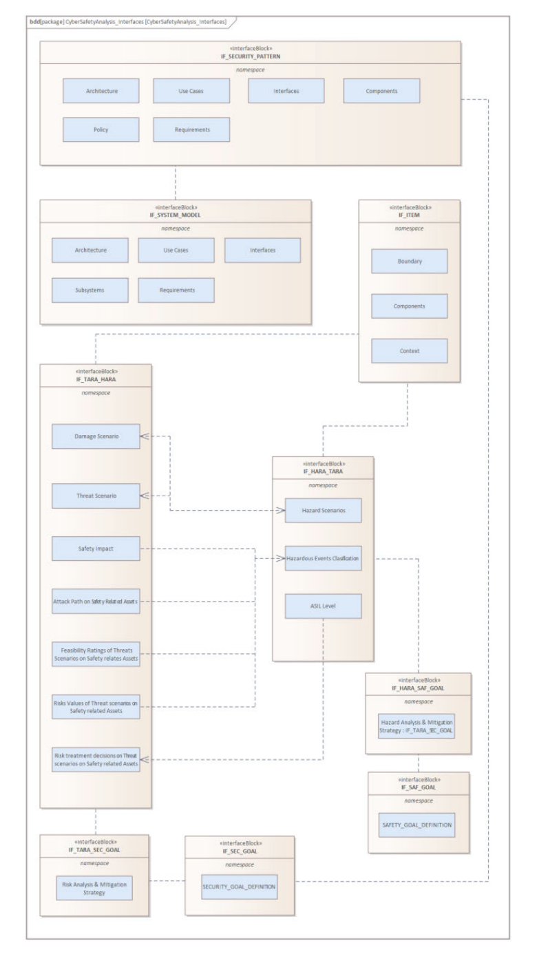 Fig. 2. CyberSafety analysis interface blocks definition and dependencies.
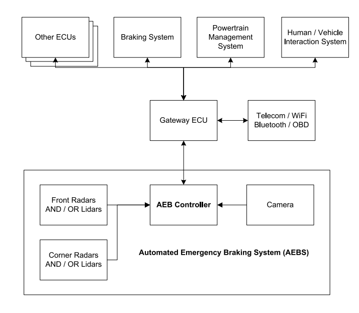
Fig. 3. The AEBS system architecture.
B. CyberSafety System Analysis
- Item Definition: Basic information about a product under development is also known as item definition. It describes what the AEBS is, what functions it performs, why it exists, how it operates and what is the trusted boundary. The purpose of this work product is to provide enough information about the item to individuals who perform the sub-phases.
Brief description of analyzed system based on [27], [28], and [29]:
Name of the product: Advanced emergency braking system (AEBS).
- Main usage of System: “The system shall automatically detect a potential forward collision, provide the driver with an appropriate warning, and activate the vehicle braking system to decelerate the vehicle with the purpose of avoiding or mitigating the severity of a collision in the event that the driver does not respond to the warning. In the case of a failure in the system, the safe operation of the vehicle shall not be endangered. During any action taken by the system, the driver can, at any time through a conscious action, e.g., by a steering action or an accelerator kick-down, take control and override the system” [39].
- Description of usage (depending on the technology): cameras, radars, lidars, or other sensors provide input data to algorithms that can activate the driver warning system or start the braking process.
- External interface: Radar (Perception sensors), HMI (Human - Machine Interaction), Powertrain system, Brake system, State Sensors (Vehicle Sensors) [6].
- Timing constraints: “collision warning [..] shall be provided at the latest 0.8 seconds before the start of emergency braking” [39].
- AEBS system commands 0.9g braking in response to a moving target [40].
- Brake rise time is subject to a brake system pre-fill and limited to 15m/s [40].
- AEBS feature is available between 5 and 80 km/h [40]
- A maximum speed reduction of 50 km/h is allowed [40]
- Safety mechanisms of braking systems will prevent AEBS to command deceleration outside the designated speed range [40].
- Framework of Joint Risk Analysis: Given our framework’s aim to address both safety and security analyses, we have opted to delineate two distinct components: a static part, rooted in the Hazard Analysis and Risk Assessment (HARA) method, and a dynamic segment, founded on Threat Analysis and Risk Assessment (TARA). Through our framework, these methods are integrated, ensuring cohesive interfaces and offering a comprehensive approach to automotive risk analysis.
a) Static risk assessment: HARA is performed based on the information contained in the item definition and considering information about other units that may affect the item and shall be defined at the vehicle level. The analysis is aimed at identifying significant hazardous events that could occur during a malfunction of the product and determining their consequences. Consequently, the effect on other functions of item malfunction should also be considered. There is no single recommended method. All supportive measures are allowed: Failure Mode and Effect Analysis (FMEA), Hazard and Operability Studies (HAZOP), brainstorming, checklists, quality history, and field studies. The following hazard analysis and risk assessment do not consider the consequences of improper behaviour of the element to material damage. Such dangers would be marked as S0 (Severity 0 “No injuries”) - and are therefore not included in the example analysis [41].
The initial stage of HARA was to identify important operating conditions for the item, such as normal traffic volume on the highway, heavy traffic in the city, sudden braking of the host automobile on the highway, and sudden braking of the host car in the city. The next stage is to identify any potential dangers that may arise as a result of system failures, e.g., unintentionally breaking (false positive), not breaking (false negative), breaking late. Using the above information, risk can be assessed for each hazard and operational situation using three attributes: Severity, Exposure and Controllability for ASIL classification as defined in [2].
Based on initial HAZOP analysis there can be some malfunctions established: AEBS activated in situations where it is not supposed to be activated and lack of intended activation of AEB when needed (Table II). For those malfunction behaviours can be potential hazards addressed: collision with cars in front or behind. For each malfunction that causes a hazard will be the driver situation analysed (speed, road, etc.) to create scenarios.
Scenario of hazardous event 1: unintended activation of AEBS function with High-speed driving (>80 km/h) in a congested traffic environment. Possibility of rear collision, hazard for driver, car passengers and following vehicle.
Scenario of hazardous event 2: lack of intended activation of AEBS function (obstacle in the way). Possibility of front collision. Hazard for driver, car passengers and for people inside the other vehicle involved in the collision.
Based on classification of hazardous events (Severity, Exposure and Controllability) information is it possible to estimate ASIL level (Table III).
TABLE II EXAMPLE OF HAZOP FOR AEBS
| Failure Mode | Enabled AEBS Function | Disabled AEBS Function |
|---|---|---|
| Loss of Function | AEBS function are not active | AEBS function active |
| Unintentionally | Enabled AEBS function when it is not supposed to be enabled | Disabled AEBS function when it is not supposed to be enabled |
| Stuck | AEBS function fails to enable | AEBS function fails to enable |
| Too Slow | Enabled AEBS function later than expected | Disabled AEBS function later than expected |
| Too Quickly | Enabled AEBS function faster than expected | Disabled AEBS function faster than expected |
b) Argumentation for severity: For our analysis we took severity classes: S0 – “No injuries, S1 – “Light and moderate injuries”, S2 – “Sever and life-threatening injuries”, S3 – “Life-threating injuries, fatal injuries” [2].
Determining severity (even for a single scenario) is at a high level of generalisation. In many cases, the real result of a scenario can be extremely different. They may depend on vehicle velocity, oncoming object velocity, type of obstacle, type of impact, gradient of slope, magnitude of delta torque, maximum acceleration/deceleration, mass of vehicle [42]. Therefore, some assumptions should be made to average the result.
For those scenarios, it was estimated that the most critical situation when the car(s) reach the highest speed (motorway) and impact of energy is also the highest.
There are different scales that define the level of severity. In this example only a categorisation of injury classes of Abbreviated Injury Scale (AIS). Categorisations such as Maximum AIS (MAIS) and Injury Severity Score (ISS) can be used but their implementation would not change the purpose and meaning of the article [40], [43], [44].
c) Argumentation for exposure: For our analysis we took severity exposure classes: E0 – “Incredible”, E1 – “Very low probability”, E2 – “Low probability”, E3 – “Medium probability”, E4 – “High probability” [2].
Exposure should give the answer for the question: “What’s the probability of exposure to hazard?” and can be estimated based on duration or frequency [1].
| Malfunction | Unintended activation of AEBS function | Lack of intended activation of AEBS function |
|---|---|---|
| Scenario | High-speed driving (>80 km/h) in a congested traffic environment | Medium speed, pedestrian crossing the road or override by another vehicle |
| Hazard | H1 - Possibility of rear collision | H2 - Possibility of front collision with obstacle on the road |
| Severity (S0–S3) | 3 | 3 |
| Exposure (E0–E4) | 4 | 1 |
| Controllability (C0–C3) | 3 | 3 |
| ASIL | D | A* |
| Safety Goal | AEBS lead to an unintended brake shall be prevented | Lack of AEBS brake when there are obstacles in front of the vehicle shall be prevented |
If several unlikely situations are combined that result in a lower probability of exposure than E1, QM may be argued for S3, C3 based on this combination [1]. The three factors (S - E - C) described below are the basis for determining the ASIL level. This, in turn, as an interface, influences the system development process by recommending technical methods used in the project.
For the first scenario (unintended activation of AEBS function), the exposure is at the should be not maximum level. It can be assumed that the most common condition when the AEBS system is not required to operate (high probability E4) but for assumed conditions (highway, follow car is not respect the safety distance or heavy track) the exposure factor is reduced (E2). For the second scenario “lack of intended activation of AEBS function” is a situation with a low probability, because it assumes the occurrence of a dangerous situation and the lack of preventive behaviour of the driver (very low probability E1). All this means that the chance of such circumstances exists, but it is much smaller than the probability that the AEBS will not be required to operate.
d) Argumentation for controllability: For our analysis we took severity controllability class: C0 – “Controllable in general”, C1 – “Simply controllable”, C2 – “Normally controllable”, C3 – Difficult to control or uncontrollable [2].
Controllability factor is used to determine the controllability class for a given hazard. An estimation of the probability that the representative driver or other persons involved can influence the situation to avoid harm is made.
There can also be sub-factors taken into account like vehicle velocity, time-to-collision (TTC), distance to obstacle, maximum, acceleration/deceleration, availability of safe area, road friction and gradient of slope [23]. For both hazardous events were the worst chosen.
TABLE IV SEVERITY DESCRIPTION [40]
| Scenario | Description |
|---|---|
| Scenario one [H1] | Unintended activation of AEBS function on highway. Rear collision possible with traffic resulting in life-threatening/severe injuries in case of side impacts/carambol - S3. AIS [Abbreviated Injury Scale] 6: extremely critical or fatal injuries such as fractures of the cervical vertebrae above the third cervical vertebra with damage to the spinal cord, extremely critical open wounds of body cavities (thoracic and abdominal cavities), etc. |
| Scenario two [H2] | Lack of intended activation of AEBS function. Front collision possible with traffic resulting in life-threatening/severe injuries in case of side impacts - S3. AIS 6: extremely critical or fatal injuries such as fractures of the cervical vertebrae above the third cervical vertebra with damage to the spinal cord, extremely critical open wounds of body cavities (thoracic and abdominal cavities), etc. |
For hazardous event 1 (unintended activation of AEBS function on motorway), the follow - driver has possibilities to avoid a collision. Also, a following car may not be able to reduce the speed (insufficient distance between vehicles, large distance needed to brake for a truck). The situation on highway is difficult to control or even uncontrollable for follows heavy tracks - C3.
For hazardous event 2 (lack of intended activation of AEBS function) function; short distance to obstacle and time to collision due to high speed - C3.
- Dynamic Risk Assessment:
a) Asset identification: The first step in the TARA is asset identification. The asset is any data, device, or other component of the environment that supports informationrelated activities in information security, computer security and network security. Hardware (e.g., servers and switches), software (e.g., mission important applications and support systems), and confidential information are examples of assets. Assets should be safeguarded against unauthorised access, use, disclosure, alteration, destruction, and/or theft, which might result in loss to the organisation. We identified the assets for the AEBS, their importance towards the CIA triad (confidentiality, integrity, authenticity), and related damage scenario (Table V).
TABLE V SUMMARY OF ASSET IDENTIFICATION AND DAMAGE SCENARIO IDENTIFICATION
| ID | Asset | Cybersecurity Property (CIA) | Damage Scenario/Hazardous Events |
|---|---|---|---|
| A1 | In-Vehicle Data Communication (Braking request) | I,A | Manipulation of in-vehicle data communication may lead to H1, H2 by an attacker |
| A2 | External Data Communication (Wi-Fi, Bluetooth, Cellular, etc.) | C,I,A | Getting control over the external vehicle communication may lead to remote triggering of H1, H2 by an attacker |
| A3 | Firmware of ADAS controller | C,I,A | Providing a non-trusted firmware may lead to triggering H1, H2 by an attacker |
| A4 | Debug Interfaces | C,I,A | Having a debug interface available may lead to uploading a non-trusted firmware and triggering H1, H2 by an attacker |
| A5 | OBD II Port communication | I,A | Manipulation of OBD communication may lead to communication issues on a vehicle bus and therefore trigger H1, H2 by an attacker |
b) Threat scenario identification: The primary emphasis was on communication between actors involved in vehicles and external interfaces. For the sake of this simple scenario, we considered both in-vehicle data communication and external data communication. Hazardous events observed during HARA were used to generate Damage Scenarios. We picked the “In-Vehicle Data Communication” asset for further thorough investigation since there a direct request to an actuator for braking is being sent, which may result in various hazards. Because information exchanged between companies engaged in the AEBS does not include any sensitive data, we identified cybersecurity qualities such as integrity and authenticity that should be considered.
Then, using the STRIDE model [45], we defined Threat Scenarios for Hazardous events H1 and H2, which have an impact on asset A1 i.e., spoofing, tampering, non-repudiation, denial of service, and elevation of privilege. Table VI contains a summary of this activity. Each of the six threat categories has a direct influence on the hazardous events H1 and H2. As a result, all of them should be evaluated for the following round of analysis.
TABLE VI THREAT SCENARIO IDENTIFICATION FOR IDENTIFIED HAZARDOUS EVENT FOR ‘IN-VEHICLE DATA COMMUNICATION’ ASSET
| Damage Scenario/Hazardous Event | Threat Scenario |
|---|---|
| H1 | Spoofing of an in-vehicle signal leads to loss of authenticity of the data communication of the braking signal request, potentially causing H1 |
| Tampering of an in-vehicle signal leads to loss of integrity of the data communication of the braking signal request, potentially causing H1 | |
| Repudiation of an in-vehicle signal leads to loss of authenticity of the data communication of the braking signal request, potentially causing H1 | |
| Denial of Service of in-vehicle signals leads to loss of availability of data communication of the braking signal request, potentially causing H1 | |
| Elevation of Privilege for the in-vehicle signal access leads to lack of sufficient authorization while logging into the ECU, which leads to malicious behavior of the braking system, potentially causing H1 | |
| H2 | Spoofing of an in-vehicle signal leads to loss of authenticity of the data communication of the braking signal request, potentially causing H2 |
| Tampering of an in-vehicle signal leads to loss of integrity of the data communication of the braking signal request, potentially causing H2 | |
| Repudiation of an in-vehicle signal leads to loss of authenticity of the data communication of the braking signal request, potentially causing H2 | |
| Denial of Service of in-vehicle signals leads to loss of availability of data communication of the braking signal request, potentially causing H2 | |
| Elevation of Privilege for the in-vehicle signal access leads to lack of sufficient authorization while logging into the ECU, which leads to malicious behavior of the braking system, potentially causing H2 |
c) Impact rating: In the following step, we determined the impact rating of each Hazardous Event H1 and H2 on Asset A1 using the Guidelines for impact ratings contained in Annex F of ISO 21434. We classified the safety effect as severe because H1 and H2 have a direct influence on vehicle safety and a threat may cause a car accident. According to our study, the privacy impact for each Damage Scenario is negligible because no confidential data is revealed. We classified the Operational and Financial Categories as Major for H1 and H2, since each of these may result in the loss of a vehicle’s important function, which may result in automobile accidents and a loss of vehicle value (Table VII). Impact rating may be classified as Negligible, Moderate, Major and Severe.
TABLE VII IMPACT RATING OF H1 AND H2 ON A1
| Damage Scenario / Hazardous Event | Impact Category | Impact Rating |
|---|---|---|
| H1 | Safety | Severe |
| Privacy | Negligible | |
| Operational | Major | |
| Financial | Major | |
| H2 | Safety | Severe |
| Privacy | Negligible | |
| Operational | Major | |
| Financial | Major |
d) Attack path analysis and attack feasibility rating: We did Attack Path analysis and Attack Feasibility evaluation for A1 immediately after effect rating for the AEBS. ISO 21434 in Annex H specifies two ways for this activity: vector-based and attack-potential-based.
We found vector-based attack strategy better suited for the concept phase since, it is not possible to collect all vulnerability information relevant elements at that stage phase. The Vector Based Attack Path and Attack Feasibility Rating study for A1 for the AEBS is summarised in Table XI in Appendix. As a result, the perception system (i.e., camera, radar, lidar), HMI (human-machine interface), and external interface (cellular network connectivity) attack paths were ranked as high, as these interfaces are easily accessible for a potential attacker, whereas ADAS (Advanced Driver Assistance Systems) is typically placed in a vehicle in an unreachable manner. For this section, we used the STRIDE model to analyse all threat scenarios and we followed the approach from ISO 21434 “Attack vector-based approach” for Attack feasibility rating.
For our example, we decided to perform the Vector Based Attack and Attack Feasibility Rating only for one Threat scenario - “Spoofing of an in-vehicle signal leads to loss of authenticity of the data communication of the breaking signal request, potentially causing H1 or H2” - because it does not necessitate expert knowledge. We used Annex F of ISO 21434 for attack feasibility evaluation, which introduced ET – elapsed time, SE – specialist expertise, KoIC – knowledge of the item or component, WoO – window of opportunity, and Eq – equipment. All parameter ratings are based on Annex G of ISO 21434. Taking into consideration all the stated characteristics, we calculated the Attack Feasibility Rating using ISO 21434. This analytical methodology gives a more complete and methodical understanding of how the final grade is determined. Similarly, to earlier methods, attack vectors for perception systems (i.e., camera, radar, lidar), HMI (humanmachine interface), and external interface (cellular network connectivity) were classified as high, hence communication between these entities must be extensively safeguarded by cybersecurity controls.
TABLE VIII RISK VALUES DETERMINATION
| Threat Scenario | Aggregated Attack Feasibility Rating | Impact Rating | Risk Value |
|---|---|---|---|
| Spoofing of an in-vehicle signal leads to loss of authenticity of the data communication of the braking signal request, potentially causing H1 | High | Severe | S:5 |
| Tampering of an in-vehicle signal leads to loss of integrity of the data communication of the braking signal request, potentially causing H1 | High | Severe | S:5 |
| Denial of Service of in-vehicle signals leads to loss of availability of data communication of the braking signal request, potentially causing H2 | High | Major | S:4 |
e) Risk value determination: The next phase in the TARA analysis is risk value determination. ISO 21434 ISO 21434 in Annex H gives an example of the use of risk matrices. According to Table H.8. Risk values can be computed by translating combinations of impact and attack feasibility ratings to risk values using risk matrices defined by the organisation. We used Annex H’s sample Risk Matrix for our AEBS. Risk vale was calculated based on equation (1), where R is defined as risk, I as impact and F as an attack feasibility.
R = 1 + I x F. (1)
We determined the final Risk Value of a Threat Scenario H1 and H2 for asset A1 using Table H.10 form [ISO 21434] which provides an example translation of impact and attack feasibility to numerical values. Table VIII shows the result. Spoofing and tampering of in-vehicle signals Risk Value, which may lead to H1, were assessed as ‘S5’ due to Severe Impact and High Attach feasibility of safety area.
f) Risk treatment decision: Finally, a risk treatment decision must be made in accordance with ISO 21434. In Table IX, we show our treatment option of choice. As all the risk values for H1 are related to safety, we opted to mitigate risks by implementing a specific security control using Security Patterns. Our chosen Security Controls/ Security Patterns are: Firewall, Symmetric Encryption, Tamper Resistance, Third Party Validator, Intrusion Detection System, System Intrusion Prevention System, DDos, Redundancy, BlackList [9].
TABLE IX RESULTS OF RISK TREATMENT DECISION
| Threat Scenario | Risk Value | Risk Treatment Option | Security Control/Security Pattern |
|---|---|---|---|
| Spoofing of an in-vehicle signal leads to loss of authenticity of the data communication of the braking signal request, potentially causing H1 | S:5 | Reducing the risk | Firewall, Symmetric Encryption, Tamper Resistance, Third Party Validator, Intrusion Detection System, Intrusion Prevention System |
| Tampering of an in-vehicle signal leads to loss of integrity of the data communication of the braking signal request, potentially causing H1 | S:5 | Reducing the risk | Firewall, Symmetric Encryption, Tamper Resistance, Third Party Validator, Intrusion Detection System, Intrusion Prevention System |
| Denial of Service of in-vehicle signals leads to loss of availability of data communication of the braking signal request, potentially causing H2 | S:4 | Reducing the risk | Firewall, DDoS Redundancy, BlackList, Intrusion Detection System, Intrusion Prevention System |
C. CyberSafety Goals Definition
The CySa description combines the safety goal, which refers to the safety situations, such as unintended AEBS activation or absence of AEBS activation, with the cybersecurity operations required to achieve the cyber safety criteria. CyberSafety Goals, like Safety and Cybersecurity Goals, have unique IDs for easy referencing.
Since the Intrusion Detection System security control is provided as a risk treatment option for all threat scenarios in our AEBS example and it fulfils CySa2 and CySa4, we chose to study it further and refine the System Model with Security Pattern, which depicts this solution. Table X represents the output of this activity.
TABLE X CYBERSAFETY GOALS DEFINITION
| CyberSafety Goal ID | Description |
|---|---|
| CySa1 | Protecting the communication between ECU’s in AEBS function to avoid unintentional activation of the AEBS function when at a safe distance from the vehicle in front. |
| CySa2 | Detecting malfunction behaviour of the AEBS to avoid unintentional activation of the AEBS function when at a safe distance from the vehicle in front. |
| CySa3 | Protecting the communication between ECU’s in AEB function to avoid the lack of deactivation of EBS function when required (obstacle in front of vehicle). |
| CySa4 | Detecting malfunction behaviour of the AEB system to avoid lack of deactivation of EBS function when required (obstacle in front of car). |
D. Applying IDS as a Security Control
1). IDS System Overview: A major security problem in networked systems, including automotive, is hostile (or at least unwanted) intrusion by users or software [46]. User intrusion can take the form of unauthorised logins or other access to the machine or, in the case of an authorised user, the acquisition of privileges or the performance of actions over and above those authorised. Intrusion detection is hardware or software-based capability to collect and analyse information from various areas within a computer or network to identify potential security breaches. The Intrusion detection system (IDS) consists of three logical components [46]:
- Sensors – responsible for data collection,
- Analysers – responsible for receiving data from one or more sensors or from other analysers. Moreover, an analyser is responsible for determining whether an intrusion has occurred,
- User Interface – allows the user to view the results of the system or to direct the system.
IDSs are often classified according to the source and type of data analysed as [46] and [47]:
- HIDS (host-based intrusion detection system) - monitors the characteristics of a single network element and the events occurring in it. In a car, a host-based IDS would reside in the various individual ECUs, monitoring incoming, outgoing traffic packets, and ensuring that they are not harmful. A HIDS also monitors the ECU to detect behaviours that indicate an intrusion.
- NIDS (network-based intrusion detection system) - monitors traffic in individual network sections or at network sites and analyses network, transport, and application protocols to identify suspicious activity. An automotive NIDS monitors all network traffic with NIDS that function as an electronic control unit, allowing it to receive and monitor all messages transmitted.
- Distributed or hybrid IDS - combines information from multiple sensors, often located on different hosts and on the network, and aggregates it in a central analyser that can better identify and respond to intrusions. An automotive distributed IDS consists of numerous of HIDS and NIDS, which are reporting the anomalies to a high computing platform, which can further send data to a backend system
IDSs generally use one of the alternative methods of analysing sensor data to detect intrusions [46], [47]:
- Anomaly detection - a collection of data on the behaviour of legitimate users over a period is collected. The current behaviour is then analysed to determine with a high degree of certainty whether the behaviour is indicative of a legitimate user or perhaps an intruder
- Signature-based or heuristic detection - uses known patterns of malicious data (signatures) or attack rules (heuristics) that are compared with current behaviour and decides whether an intruder is present. This is also known as misuse detection. This method can only identify known attacks for which there are known patterns or rules.
Currently there are efforts in the automotive industry to standardise the IDS solution. The AUTOSAR consortium introduced the common strategy of implementation the IDS system into the in-vehicle communication system [48]. To safeguard user information gathered for Intrusion Detection Systems (IDS), it’s essential to assess the data’s sensitivity and regulatory requirements through a privacy study. Various approaches, like anonymization and encryption using modern cryptographic methods, ensure data protection. Secure storage methods, such as using Hardware Security Modules (HSMs) and adhering to industry standards like AUTOSAR, provide guidance on managing stored data securely within automotive systems.
2). IDS Pattern Application Into the System Model: We employed the Signature-based IDS pattern to evaluate our model, which specifies malicious activities in advance. This solution is simpler for the in-vehicle IDS system to implement, needs less computer resources, and does not involve machine learning techniques. As a result, even with limited processing capacity, it can be simply applied to all critical parts of the system. In contrast to [9], we chose to change the IDS pattern structure and include IDS manager (IdsM) and IDS Router(IdsR) to better represent the AUTOSAR standard [48]. IdsM is responsible for the security events propagation to the IdsR, while IdsR forwards the data to the backend system for further analysis. Each IdsM instance consists of IDS Core, Event Processor, Attack Detector, Signature Information, Signature and Response. Every ECU, which is a crucial component of a system, should have an IdsM instance. The key pattern constraints are the possible increase in message delay and additional development costs. On the other hand, it satisfies the market regulation UNECE R155 [49] and raises the system’s cybersecurity level.
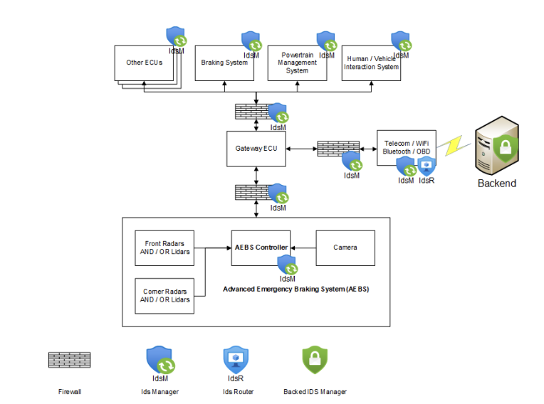
Fig. 4. System model refinement with intrusion detection system elements.
E. System Model Refinement
After implementing the IDS pattern, the next crucial step was to update the system model to incorporate it. The IDS pattern introduced the IdsM instance responsible for detecting malicious activity in critical system components such as the Braking System, Power Management System, Human/Vehicle Interaction System, Gateway ECU, Telematic Module, and AEB controller. Additionally, since a firewall is typically established between different vehicle domains, we included it in our model as well. The firewall serves as an additional layer of protection and can identify potential dangers, making it necessary to install an IdsM instance within the firewall.
To report any detected harmful behaviours to the backend system, the IdsR component is installed in the Telematic ECU with its resolute IdsM instance. This setup enables effective communication between the IdsR and the backend system for further analysis and response. Lastly, the backend system comprises the IDS Manager, which leverages machine learning algorithms to analyse data collected from the vehicle fleet. This IDS Manager plays a crucial role in identifying patterns and anomalies in the data, enhancing the overall intrusion detection capabilities of the system.
By incorporating these IDS components into the system model, we establish a robust infrastructure for detecting and mitigating potential intrusions in the automotive system. This updated system model enables effective monitoring of critical components, facilitates communication between different system elements, and leverages advanced analytics for comprehensive threat detection and response.
The next step was to update the system model after implementing the IDS pattern. The IdsM instance in charge of malicious activity detection is found in critical system components such as the Braking System, Power Management System, Human/Vehicle Interaction System, Gateway ECU, Telematic Module, and AEB controller. Because a firewall is generally established between different vehicle domains, we include it in our model as well. Since the firewall may identify a possible danger, the IdsM instance should be also installed there. IdsR, which oversees reporting harmful behaviours to the backend system, is installed in the Telematic ECU with its own resolute IdsM instance. Finally, the backed system contains the IDS Manager, which can analyse data from the vehicle fleet using machine learning algorithms. Fig. 4.
V. DISCUSSION AND CONCLUSION
The automotive sector is undergoing a major paradigm change as it transitions from a product-based to a serviceoriented industry. With the advent of car electrification and autonomy, there is an increased need to secure the communication and data interchange in vehicles. Cybersecurity protection cannot be treated as an optional feature but should be integrated into the design concept from the beginning of a product’s lifespan. By following a security-by-design approach, product cybersecurity and safety can be significantly improved. Collaboration between unique design disciplines, such as functional safety (FS) and cybersecurity (CySe), is crucial in achieving this goal. Artificial Intelligence (AI) may also serve a pivotal role in a secure design process. Integrating AI into automotive design enhances cybersecurity and safety by automating test case generation, customer requirement analysis, secure coding assistance, vulnerability identification, and patch development. These AI-driven tools strengthen automotive systems against cyber-attacks, reinforce safety measures, and assist in verification and validation throughout the vehicle lifecycle. The future works may focus on AI support in secure system design as well.
Our research has focused on integrating security patterns, defining interfaces, and property flows between cybersecurity and safety in the automotive sector. Using MBSE approach, we have demonstrated the potential for enhanced collaboration between CySe and FS disciplines, leading to improved system models.
Our CyberSafety Design Framework, leveraging MBSE, offers a systematic approach to integrating cybersecurity and functional safety features. By conducting HARA and TARA concurrently, we can significantly reduce and improve analysis efforts, resulting in a more efficient and comprehensive development process for automotive systems architecture.
Our research has focused on the concept level, recognizing that detailed technical implementation can vary significantly across the industry. Thus, our approach aims to provide a clear and adaptable framework without delving into specific technicalities.
The proposed CyberSafety Design Framework was rigorously evaluated and through a case study focused on the Advanced Emergency Braking System (AEBS).
We are pleased to report that the proposed approach was validated indirectly during the focused group interview. The expert evaluation was chosen due to the lack of a possibility to design the same system using two different approaches and due to the time and resource consumption of such a class system design and development process.
TABLE XI VECTOR BASED ATTACK PATH AND ATTACK FEASIBILITY RATING ANALYSIS FOR A1
| Threat Scenario | Attack Path | Attack Feasibility Rating |
|---|---|---|
| Spoofing of an in-vehicle signal leads to loss of authenticity of the data communication of the braking signal request, potentially causing H1 or H2 | 1. Attacker compromises perception systems (cameras, radar, lidars, GPS sensors) ECUs. 2. Spoofed signals from perception systems are forwarded to ADAS ECU. 3. ADAS ECU sends braking request to Braking System. 4. a. Unintended activation of AEB function. b. Lack of intended activation of AEB function. | High |
| 1. Attacker compromises an HMI system ECU. 2. Spoofed signals from the HMI system are forwarded to ADAS ECU. 3. ADAS ECU sends braking request to Braking System. 4. a. Unintended activation of AEB function. b. Lack of intended activation of AEB function. | High | |
| 1. Attacker compromises an ADAS ECU. 2. Spoofed signals are sent to Brake System. 3. a. Unintended activation of AEB function. b. Lack of intended activation of AEB function. | Low | |
| 1. Attacker compromises connectivity ECU from cellular network. 2. Spoofed signals from Connectivity ECU are forwarded to ADAS ECU. 3. ADAS ECU sends braking request to Braking System. 4. a. Unintended activation of AEB function. b. Lack of intended activation of AEB function. | High | |
| Tampering of an in-vehicle signal leads to loss of integrity of the data communication of the braking signal request, potentially causing H1 or H2 | 1. Attacker compromises perception systems (cameras, radar, lidars, GPS sensors) ECUs. 2. Tampered signals from perception systems are forwarded to ADAS ECU. 3. ADAS ECU sends braking request to Braking System. 4. a. Unintended activation of AEB function. b. Lack of intended activation of AEB function. | High |
| 1. Attacker compromises an HMI system ECU. 2. Tampered signals from the HMI system are forwarded to ADAS ECU. 3. ADAS ECU sends braking request to Braking System. 4. a. Unintended activation of AEB function. b. Lack of intended activation of AEB function. | High | |
| 1. Attacker compromises an ADAS ECU. 2. Tampered signals are sent to Brake System. 3. a. Unintended activation of AEB function. b. Lack of intended activation of AEB function. | Low | |
| 1. Attacker compromises connectivity ECU from cellular network. 2. Tampered signals from Connectivity ECU are forwarded to ADAS ECU. 3. ADAS ECU sends braking request to Braking System. 4. a. Unintended activation of AEB function. b. Lack of intended activation of AEB. | High | |
| Information disclosure leads to breaking the confidentiality of data communication | Since there is no confidential data sent to the Braking System this threat is not considered. | N/A |
| Denial of Service of in-vehicle signals leads to loss of availability of data communication of the braking signal request, potentially causing H2 | 1. Attacker compromises perception systems (cameras, radar, lidars, GPS sensors) ECUs. 2. A large number of signals from perception systems are forwarded to ADAS ECU. 3. ADAS ECU is blocked due to too many requests from perception systems. 4. Lack of intended activation of AEB function. | High |
| 1. Attacker compromises an HMI system ECU. 2. A large number of signals from the HMI system are forwarded to ADAS ECU. 3. ADAS ECU is blocked due to too many requests from perception systems. 4. Lack of intended activation of AEB function. | High | |
| 1. Attacker compromises an ADAS ECU. 2. Too many signals are sent to Brake System. 3. Lack of intended activation of AEB function. | Low | |
| 1. Attacker compromises connectivity ECU from cellular network. 2. A large number of signals from Connectivity ECU are forwarded to ADAS ECU. 3. ADAS ECU is blocked due to too many requests from perception systems. 4. Lack of intended activation of AEB function. | High | |
| Elevation of Privilege for the in-vehicle signal access leads to lack of sufficient authorization while logging into the ECU, which leads to malicious behavior of the braking system, potentially causing H1 or H2 | 1. Attacker compromises ADAS ECU and logs into the operating system. 2. Attacker gets root/admin access rights. 3. ADAS ECU sends braking request to Braking System. 4. a. Unintended activation of AEB function. b. Lack of intended activation of AEB function. | Low |
The focused group comprises two types of international participants: researchers focused on the automotive embedded systems design and practitioners (representatives of OEMs and suppliers). The group believed the proposed approach could support the safety and security improvement of the designed system. Additionally, practitioners, representatives of big automotive companies, expressed the view that the proposed approach could help to reduce the time and resources spent on system design and development.
In this study, we successfully applied the Signature Based Intrusion Detection System (IDS) pattern, which is deemed mandatory under UNECE Regulation No. 155 [49]. The integration of this IDS pattern was driven by both regulatory requirements and market demands, emphasizing the critical role of intrusion detection systems in addressing cybersecurity challenges in modern vehicles. By demonstrating the effective application of the IDS pattern within our framework, we have further solidified the framework’s practicality and relevance in real-world automotive applications. This successful evaluation showcases the framework’s potential to enhance collaboration between cybersecurity and functional safety disciplines, laying the foundation for creating safer and more secure automotive systems. However, it is important to acknowledge that security patterns for cybersecurity are still evolving, and further revisions are needed to meet market demands. Effective utilization of the pattern needs expert knowledge. Currently, their deployment into system design process is conducted manually. There are some works focused on the automation of the patterns utilization in the system architecture design process [52], [53].
A key insight gained from this study is the importance of performing all analyses within a single model and in the same tool. The integration of various analysis efforts in a unified platform streamlines the process, reducing overhead and facilitating better communication and decision-making.
As we look towards the future, we envision standardization efforts that involve the introduction of security patterns into cybersecurity standards. This would complement existing efforts in standardization working groups related to Cybersecurity Assurance Level (CAL) and Targeted Attack.
Feasibility (TAF) in ISO/SAE 8475, as well as Cybersecurity Verification and Validation in ISO/PAS 8477 and Information Security, Cybersecurity, and Privacy Protection in ISO/IEC 5888.
In summary, our research has contributed to the advancement of automotive cybersecurity and safety by highlighting the potential benefits of MBSE methodologies, seamless collaboration between CySe and FS, and the importance of integrating security patterns into cybersecurity standards. Furthermore, the CyberSafety framework approach, as presented, can serve as an effective means of introducing a comprehensive approach to a holistic risk analysis. Here, cybersecurity patterns facilitate the utilization of well-known, proven solutions, enhancing the overall robustness of the risk analysis process. As we continue our efforts, we aim to further refine our framework, explore Safety of the Intended Functionality (SOTIF) use cases, and embrace advancements in the domain, ensuring the highest levels of safety and security in vehicles.
APPENDIX
See table XI.
ACKNOWLEDGMENT
This work was created as part of AGH University of Science and Technology’s Implementation Doctorate Program.