Chapter 4: Real-time control systems
UNDERSTANDING CONTROL SYSTEM
https://www.youtube.com/watch?v=2BwUMk10WqI
OBJECTIVES
- Introduction
- Components in real-time control systems
- Real-time control systems in autonomous vehicles
- Conclusions and future directions
1. INTRODUCTION
- A control system consists of a set of devices that senses, alters or modulates the behaviours or tunable parameters of the controlled plant such that the desirable states of the plant are achieved.
- In a vehicle, a control system can range from the temperature control of the air conditioner to the stability control of the vehicle motion.
- Advanced real-time control systems interpret and analyse sensory information to identify appropriate navigation paths to the desired destination, as well as obstacles and relevant signage, ensuring safe and efficient travel.
2. COMPONENTS IN REAL-TIME CONTROL SYSTEMS:
2.1 TYPICAL REAL-TIME CONTROL SYSTEM
- A real-time control system is a control system that ‘controls an environment by receiving data, processing them, and returning the results sufficiently quickly to affect the environment at that time’.
- In a control system, ‘real-time’ means the programs run by the controller must be fast enough to generate response within specified time limits, often referred to as ‘deadlines’.
- Such limits or constraints are always in the order of milliseconds or even microseconds.
- For a real-time controller, the hardware scan cycle must be short enough, and the program should be well designed in order that the input scan, program executing and output scan can be completed within a scan cycle.
2.1.1 SMART TRAFFIC LIGHT CONTROL SYSTEMS
- Smart traffic lights (or intelligent traffic lights) form a real- time traffic control system by combining traditional traffic lights with an intelligent signal control system.
- The signal control system uses an array of sensors to detect traffic density and adjusts traffic lights via artificial intelligence to increase traffic efficiency and safety.
2.1.2 AUTOPILOT SYSTEMS
- An aircraft autopilot (automatic pilot) system controls the aircraft without the pilot directly operating the controls.
- Such system is developed to reduce the work load of human pilots in order to lessen their fatigue and reduce operation errors during long flights.
- It handles most of the time-intensive nonedecision-making tasks, helping the human pilots to focus on the overall status of the aircraft and flight.
- The control software reads the aircraft’s current speed, pose, height and location and then issues control signal to a flight control system, which is a lower-level actuator controller, to adjust the control surfaces of the aircraft in order to maintain the aircraft’s attitude, height and speed while guaranteeing the lateral, vertical and longitudinal stability.
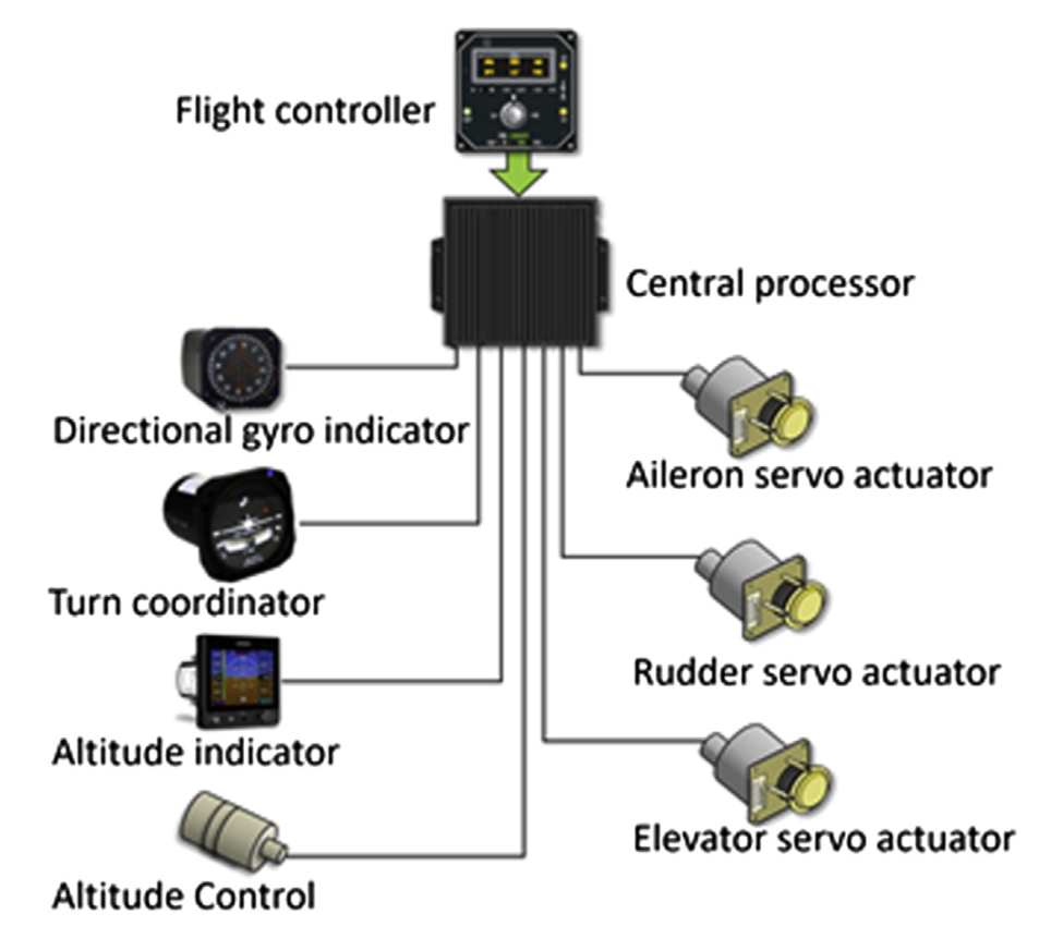
Figure 4.2 An aircraft autopilot system.
2.2 STRUCTURE OF THE REAL-TIME CONTROL SYSTEM OF AUTONOMOUS VEHICLES
- The implementation of real-time control for an autonomous vehicle relies on a series of components, and each of these components performs a different role.
- Some of them act as the ‘brain’ to coordinate and make decisions and we call them ECUs; some of them are responsible for collecting the external and internal information and we call them sensors; some of them are responsible for executing commands from ECUs and we call them actuators; some of them play as information-transmitting channels and we call them communication bus.
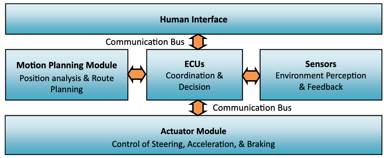
Figure 4.3 Components in real-time control system for an autonomous vehicle. ECUs, elec- tronic control units.
2.3 ELECTRONIC CONTROL UNITS
- Electric Control Unit (ECU) refers to dedicated vehicular embedded microcontrollers that controls one or more of the electrical systems or subsystems in a vehicle.
- Types of ECU include central control module, engine control module, powertrain control module, transmission control module, electronic brake control module, speed control unit, body control module, suspension control module, humanemachine interface, telematic control unit, brake control module (including Anti-lock Braking System (ABS) and Electronic Stability Control (ESC)), battery management system, door control unit and seat control unit. Some modern motor vehicles have up to 80 ECUs.
2.4 SENSORS IN AUTONOMOUS VEHICLES
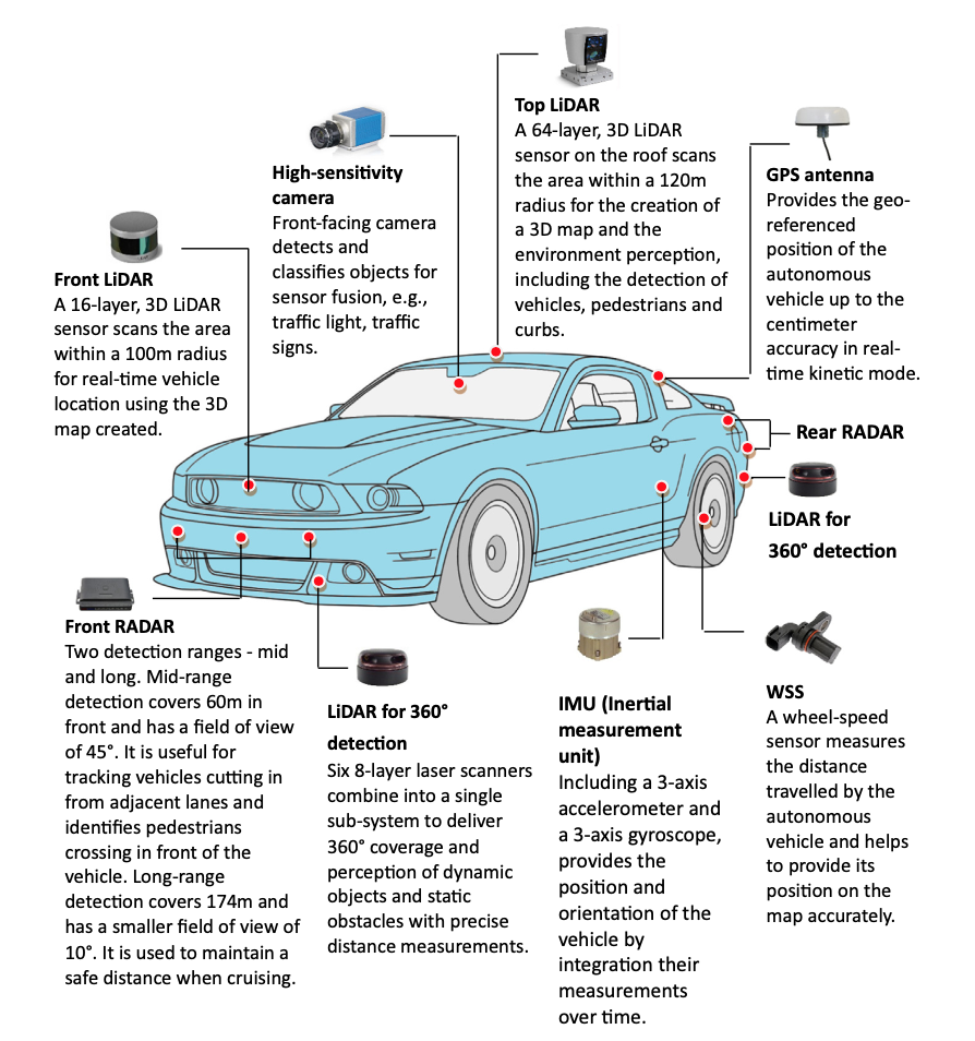
Figure 4.4 Sensors in an autonomous vehicle.
2.4.1 ULTRASONIC SENSORS
- An ultrasonic sensor is a device that can measure the distance by using ultrasonic waves.
- It works by sending out an ultrasonic wave at a specific frequency and receiving the wave reflected back from the target.
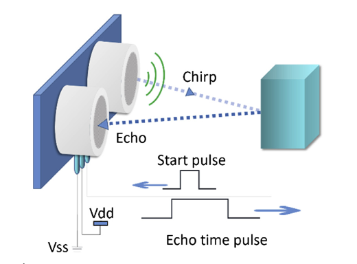 Figure 4.5 Ultrasonic sensor.
2.4.2.3 DIFFERENT USES OF RADIO DETECTION AND RANGING SENSOR IN AUTONOMOUS VEHICLES
Table 4.1 The Different Applications for Radio Detection and Ranging Sensors in Autonomous Vehicles
| Application | Detection Range | Field of View | Technology |
|---|---|---|---|
| Adaptive cruise control (ACC) | 150 ~ 200 m | +-10 ~ 20 degrees | Single beam, 24 GHz |
| Forward collision warning and precrash detection | 40 ~ 90 m | +-35 ~ 45 degrees | Single beam,76 GHz/24 GHz |
| Blind spot detection, lane change assist and cross-traffic detection | 30 ~ 40 m | +-40 ~ 50 degrees | Single beam, 76 GHz/24 GHz |
| ACC with stop and go | Multiple ranges | Multiple ranges | Multimode electronically scan |
2.4.6.2 REAL TIME KINEMATIC GLOBAL POSITIONING SYSTEM
- RTK (real time kinematic) satellite navigation is a technique used to enhance the precision of position data obtained from standard GPS systems.
- The accuracy of the GPS may be affected by many contributing factors like clock difference between satellites, refraction of electromagnetic waves in ionosphere, random noise added to clock in commercialised GPS signal, not enough satellites (less than 8 w 9), and signal bounced off buildings or canyons.
- A good way to correct these variable errors is to set up a fixed GPS receiver as a base station whose position can be measured.
2.4.6.2 REAL TIME KINEMATIC GLOBAL POSITIONING SYSTEM
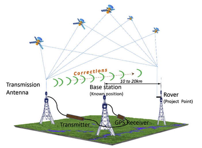
Figure 4.11 Real time kinematic global positioning system (GPS).
2.5 ACTUATORS
- For any control system, the actuators are the terminal components which are responsible for moving or controlling the system.
- In modern vehicles, there are various actuators like motors, valves and hydraulic cylinders.
- These actuators act as ‘movers’ to execute the steering, gear changing, braking, etc.
3. REAL-TIME CONTROL SYSTEMS IN AUTONOMOUS VEHICLES
Figure 4.14 General structure of autonomous vehicle real-time control system.
3.1.2 LOCALISATION
- The localisation for autonomous vehicles includes tasks at three different levels: road-level localisation, lane-level localisation and feature-level localisation.
- The road-level localisation provides the rough estimation of the vehicle position in an existing road map.
- This level of localisation can be achieved by utilizing the position information provided by a GPS system.
- However, the refreshing rate of civil-level GPS devices (normally lower than 1 Hz) and the accuracy (~3 m) are not sufficient for autonomous driving.
- To achieve lane-level localisation, sensory information from IMUs and wheel speed sensors needs to be fused together with the raw position information to provide higher-positioning refreshing rate (>20 Hz) and accuracy (<0.5 m).
- Combining this fused position information with an existing road lane map, the vehicle’s current lane selection on a road can be identified.
3.3.4 NEURAL NETWORKEBASE D ADVANCED CONTROL
- Besides the traditional control models mentioned above, there are new motion plan and control methods emerging in the past two decades.
- These methods can have more complex behaviour patterns and better performance.
- In NN-based control model, an NN is used to control the motion of the vehicle. The NN needs to be trained with human driving data before it can be used to control the vehicle. A trained NN will mimic the human driver’s behaviour in the training data.
- The input to an NN can be the same as the analytical-based approach, namely, extracted features from the perception modules
- The input to an NN can also be the raw sensory data, for example, the video frames from a camera. In this case a deep NN, which is normally a CNN, needs to be adopted.
3.3.4 NEURAL NETWORK-BASED ADVANCED CONTROL
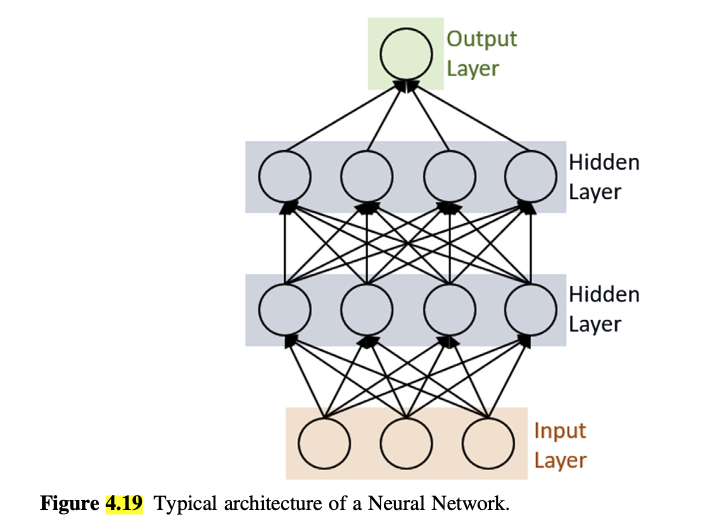 Figure 4.19 Typical architecture of a Neural Network.
3.3.6 MODEL PREDICTIVE CONTROL
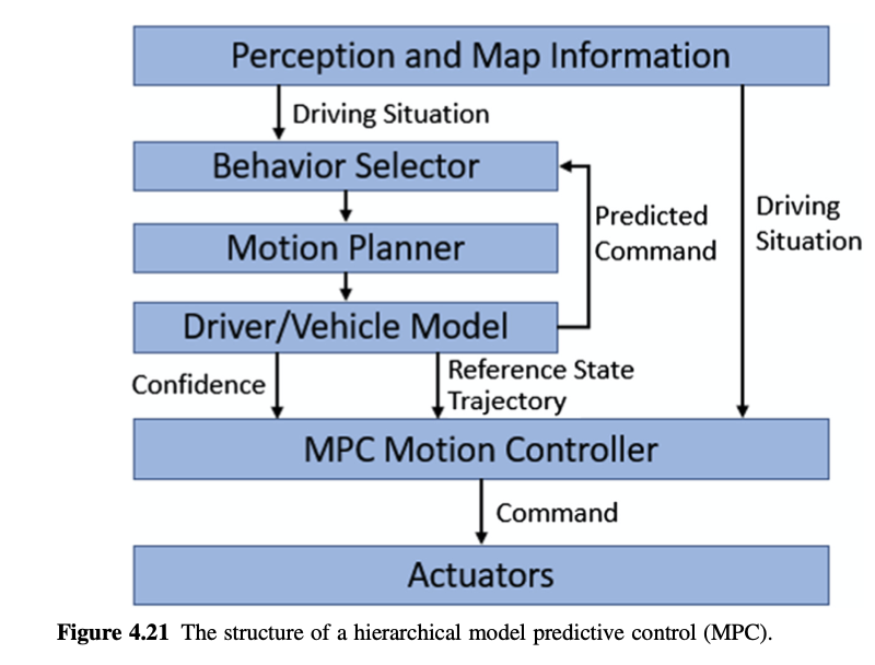
Figure 4.21 The structure of a hierarchical model predictive control (MPC).
3.4 AUTONOMOUS VEHICLE COLLABORATION IN TRANSPORTATION CYBER-PHYSICAL SYSTEM
- In the scenario where level 5 fully autonomous driving is achieved, autonomous vehicles will not function as independent individuals but rather form a cyber-physical network where all vehicles and infrastructures are connected.
- Under this situation, the motion planning and control system may still work similarly, as today, but the perception and mission planning systems will encounter a big reform.
- The basic methods will not be changed, but the scale and accuracy of the surrounding map built by the perception system will be improved a lot with the help of excessive information exchanged between vehicles and infrastructures.
3.4.1 COMMUNICATION IN TRANSPORTATION CYBER-PHYSICAL SYSTEM
To form the cyber-physical network of vehicles and infrastructures, special communication methods need to be adopted.
Unlike normal networks, vehicles are always moving around and causing the structure of the network to change.
The first challenge lies in the communication quality between vehicles and infrastructures.
Although there is a dedicated short-range communication system designed for this application, more problems still need to be solved.
For instance, when traffic is heavy, a large number of vehicles may transmit information at the same time and that can interfere with each other’s communication.
The second challenge lies in the structure of the network.
It is not realistic to include all vehicles and infrastructures under the same network all the time due to the dynamics in the network; An effective method is grouping the nearby vehicles and infrastructures under a low- level network.
3.4.2 VEHICLE TO VEHICLE COLLABORATION
With the communication system ready, the collaboration between vehicles can be performed by conducting mission planning based on shared perception information between vehicles.
This type of collaboration can be very helpful under both highway and urban driving scenarios.
With extra perception information, mission planning system can plan more ahead for potential dangers.
Moreover, by sharing mission plan information between each other, a vehicle can learn not only the behaviours but also the reasons for the behaviours of surrounding vehicles, which will significantly reduce unnecessary overshoot or correction in mission plan.
In urban driving scenario, vehicle to vehicle collaboration can also improve driving safety by sharing perceived obstacle information, especially moving obstacles, for example, pedestrians and cyclers.
3.4.3 VEHICLE TO INFRASTRUCTURE COLLABORATION
- The collaboration between vehicles and infrastructures benefits urban driving.
- Since infrastructures, for example, traffic lights, RADARs and cameras, are fixed over the road or along the roadside, they can have much more accurate observations of the environment than the moving vehicles.
- Vehicles that may drive through a congested area can then reschedule its route in advance.
- Around sharp corners where vehicle onboard sensors may have limited field of vision, cameras mounted on the roadside can help to detect children running across and prevent the happening of accidents by sending a warning to passing-by vehicles.
- At intersections, the traffic light can share its state to vehicles that are planning to pass it.
- The vehicles can make adjustment in their mission planner to avoid sudden brake or acceleration.
- In certain area where human drivers are not presenting, the traffic lights can even be removed to save infrastructure construction cost.
4. CONCLUSIONS AND FUTURE DIRECTIONS
- As a typical CPS system, autonomous vehicles incorporate the three essential factors of computing, communication and control.
- Among the three factors, the real-time control system is the most sophisticated due to the involvement of various components and functions.
- Based on the hardware platform constructed by ECUs, sensors and communication buses, each required function is implemented in a form of embedded software.
- Instead of a large constellation of sensors working together, future autonomous vehicles will be a real intelligent system, which is the ultimate goal of the autonomous vehicle CPS.
- In order to enable autonomous driving functions, the vehicle should rely on the combination of different sensors to perceive the environment with a very high precision and reliability.
- However, each sensor technology has its own shortcomings and capability limitations, e.g., some of them may be impaired in bad weather scenarios.
- These shortcomings make it difficult for any of the sensors to be used as a standalone system.
- Moreover, the failure of one or more sensors will possibly result in the malfunction of the autonomous vehicle control system.
- One way to minimize this is to ‘fuse’ the data emanating from various sources.
- This is commonly known as sensor fusion.
- A fused sensor system combines the benefits of multiple sensors, i.e., RADARs, LiDARs, GPS and cameras, to construct data sources with redundancies.
- In addition, to make the real-control system more robust, fault diagnosis, tolerance control and the sensorless estimation technology also need to be further researched and applied in the TCPS.
- Fully autonomous vehicles and intelligent connected vehicles will be the features of future ground transportation.
- Humanevehicle interaction and riding comfort will also be the goals of autonomous driving system, as well as of all the autonomous functions.