Chapter 3: Collaborative modelling and co-simulation for Transportation Cyber-Physical Systems
INTELLIGENT TRANSPORT SYSTEM - IOT IN TRANSPORT AND TRAFFIC MANAGEMENT
- https://www.youtube.com/watch?v=vEi-1981XFs
OBJECTIVES
- Introduction
- Transportation Cyber-Physical Systems engineering
- The model-based cyber-physical system engineering context
- Towards an integrated tool chain for cyber-physical system engineering
- An example of co-modelling: railway interlocking system
1. INTRODUCTION
- Sustainable transportation, especially in increasingly urbanized environments, relies on mobility being a flexible service that can respond to changes in the environment as well as the behavior and needs of users.
- Delivering such responsiveness requires future transportation systems to be "smart," relying on digital technologies for the acquisition, transmission, and analysis of data from physical systems.
- The systems engineer working in the transport environment faces many challenges alongside the demands of a complex, multi-owner environment.
- The cyber-physical character of transportation projects means that we must deal with network-distributed processes and in integrating the variety of design models and analytic techniques used by the many disciplines that collaborate (intentionally or otherwise) in delivering mobility.
2. TRANSPORTATION CYBER-PHYSICAL SYSTEMS ENGINEERING
- Together with energy, transport is a key driver of our economy and way of life.
- There is increasing emphasis on adopting more sustainable and clean mobility solutions that would allow us to continue on our path of growth and prosperity.
- Intelligent systems are providing a shift to user-centric mobility that integrates inadequately connected mode-based systems while allowing system-wide optimisation of networks and resources.
- Ageing society, energy usage, carbon footprint, network resilience and socioeconomic aspects are all key transport challenges being reimagined through digitalisation.
2.1 NEW MOBILITY CONCEPTS
Mobility as a Service (MaaS)
- a technology-enabled Mobility Management service where the customer interface and business back office are integrated [.]. MaaS concentrates on resolving the origin and destination requirements of the traveller through providing (usually) a number of options which vary by mode, time and cost.
- At a fundamental level, future transport seems to be moving towards models that are based around access rather and ownership, with the service provision being at the core and the mode used to offer that service being irrelevant.
- In other words, transport is expected to become modally agnostic, with an integration of private and public transport where digitalisation would make possible to imagine scalable doorto-door services without the need of owning a car.
2.2 CYBER- PHYSICAL SYSTEM ENGINEERING IN TRANSPORTATION
- Systems thinking is fundamental in fulfilling the technical, societal, economic and urban impact that data-driven and digitally enabled technologies and methodologies can have in the future of transport of people and goods.
- Cyber-physical systems (CPSs) use open network technologies, e.g., the Internet with the characteristics that include among others (1) systems of collaborating computational elements controlling physical entities, (2) interconnections between virtual and physical models, (3) systems of systems and (4) ability for autonomous behaviour, e.g., self-control/self-optimization.
- Air traffic control could be transformed from current fixed corridor approaches to a more fluid and flexible model allowing for higher capacity.
- On the roads, solutions such as vehicle to infrastructure and vehicle to vehicle (V2V) are key examples of the direction that innovation is taking in this sector.
2.3 MULTIDISCIPLINARY ASPECTS OF TRANSPORTATION CYBER-PHYSICAL SYSTEM
Transport systems are complex sociotechnical systems.
A set of rules, cognitive routines, shared beliefs, social norms and conventions, regulations, industry standards, protocols, contracts, laws, and so forth that fulfill a societal function (e.g., everyday mobility) and thereby condition the practices through which the technology, infrastructure, markets, cultural values, user practices, maintenance and repair, regulation, and formal knowledge that make up sociotechnical systems are reproduced.
Addressing these physical (e.g., infrastructure, maintenance) and cyber (e.g., technology such as traffic control systems) aspects and their intertwined connections demands a collaborative multidisciplinary approach, which is arguably at its most relevant when attempting to design and apply complex CPS engineering concepts.
3. THE MODEL- BASED CYBER- PHYSICAL SYSTEM ENGINEERING CONTEXT
- CPS engineering is a highly active area of research and development.
- The extensive Road2CPS roadmapping exercise identifies strong drivers for change in the transportation sector, including the rise of artificial intelligence techniques, and increasing computing and network capabilities.
- However, the report also recognises the need for coordination among diverse systems and disciplines in the sector, particularly the need for networks and applications that ‘enable the whole transport ensemble to operate effectively and efficiently’.
- It states a priority to ‘generate improved tool support for heterogeneous modelling techniques, including model management and traceability support, and the ability to consider models of different levels of granularity and abstraction in appropriate relationships to each other’.
- Mechanical and control engineers typically model in continuous- time (CT) formalisms described through differential equations.
- Conversely, software engineers use discrete-event (DE) formalisms to model and analyse these supervisory aspects but often lack the ability to test them against realistic, real-time test data.
- Current model-based design tools tend to focus on a single formalism, hindering the integration of heterogeneous models from multiple sources.
- The design of CPSs clearly requires these methods to be brought together to tackle their inherent heterogeneity, and there is an identified ‘need to facilitate the integration of models and simulations across multiple domains and disciplines’.
- Collaborative modelling (co-modelling) is a promising approach in which diverse models are connected together in a co-model that can be analysed through cosimulation.
- This allows individual engineering disciplines to use notations that are well established within their domains, provided they can produce simulators that conform to the interface constraints for the co-simulation framework.
TOWARDS AN INTEGRATED TOOL CHAIN FOR CYBER-PHYSICAL SYSTEM ENGINEERING
4.1.1 Models
- A model is a (potentially partial and abstract) description of a system, limited to those components and properties that are pertinent to the purpose for which the model is being constructed.
- In a CPS model, we model systems with cyber, physical and network elements.
- These elements may be modelled in a variety of languages, with different notations, concepts, levels of abstraction and semantics, which are not necessarily easily mapped one to another.
- A design parameter is a property of a model that can be used to affect the model’s behaviour but remains constant during a given simulation.
- A variable is feature of a model that may change during a given simulation.
4.1.2 System architecture
- An architecture ‘defines the major elements of a system, identifies the relationships and interactions between the elements and takes into account process’.
- In a CPS architecture, elements may be either cyber or physical, corresponding to some functional logic or an entity of the physical world, respectively.
- Within an architecture, an interface may describe both digital and physical interactions: digital interfaces contain descriptions of operations and attributes that are provided and required by components.
- Physical interfaces describe the flow of physical Within an architecture, an interface may describe both digital and physical interactions:
- digital interfaces contain descriptions of operations and attributes that are provided and required by components. Physical interfaces describe the flow of physical matter (for example, fluid and electrical power) between components.matter (for example, fluid and electrical power) between components.
4.1.3 Analytic techniques
- Co-simulation is the simultaneous, collaborative, execution of models.
- The models may be CT, DE or a combination and are regarded as simulation units in that they may be executed.
- A Co-simulation Orchestration Engine (COE) is an implementation of a Master Algorithm that manages the exchange of data and the progression of time in each of the constituent simulations so that they together deliver a coherent holistic simulation of the CPS.
- A COE can also allow real software and physical elements to participate in co-simulation alongside models, enabling both hardware-in-theloop (HiL) and software-in-the-loop (SiL) simulation.
- Design space exploration (DSE) is the process of building and evaluating comodels in order to select a design that satisfies an objective from a space of alternatives.
- Test automation (TA) is the machine-assisted automation of system tests.
- In a co-modelling setting, we are able to focus on testing system models against the requirements on the system.
4.2 TOWARDS A TOOL CHAIN FOR CO-MODELLING
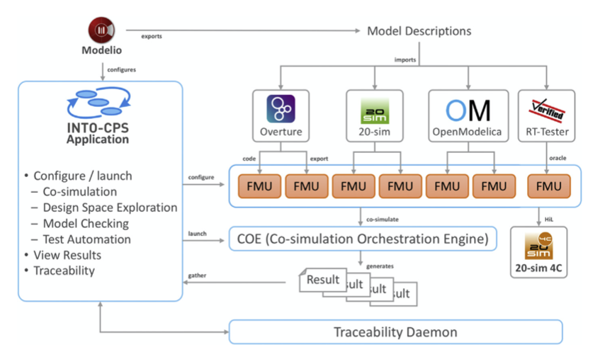
Figure 3.1 The integrated tool chain for CPS (INTO-CPS) tool chain. FMU, Functional Mock- up Unit.
4.3 MODELLING TECHNOLOGIES
4.3.1 OpenModelica
- Modelica is an object-oriented equation-based language for describing physical systems, including, for example, mechanical, electrical and hydraulic phenomena.
- OpenModelica is an open-source environment supporting models written in the Modelica language.
- It also supports the graphical of equations through blocks that have input and output ports, which are then connected to form a model of the component or system.
- OpenModelica provides static checking of Modelica models, including syntax and type checking, and dynamic debugging through breakpoints.
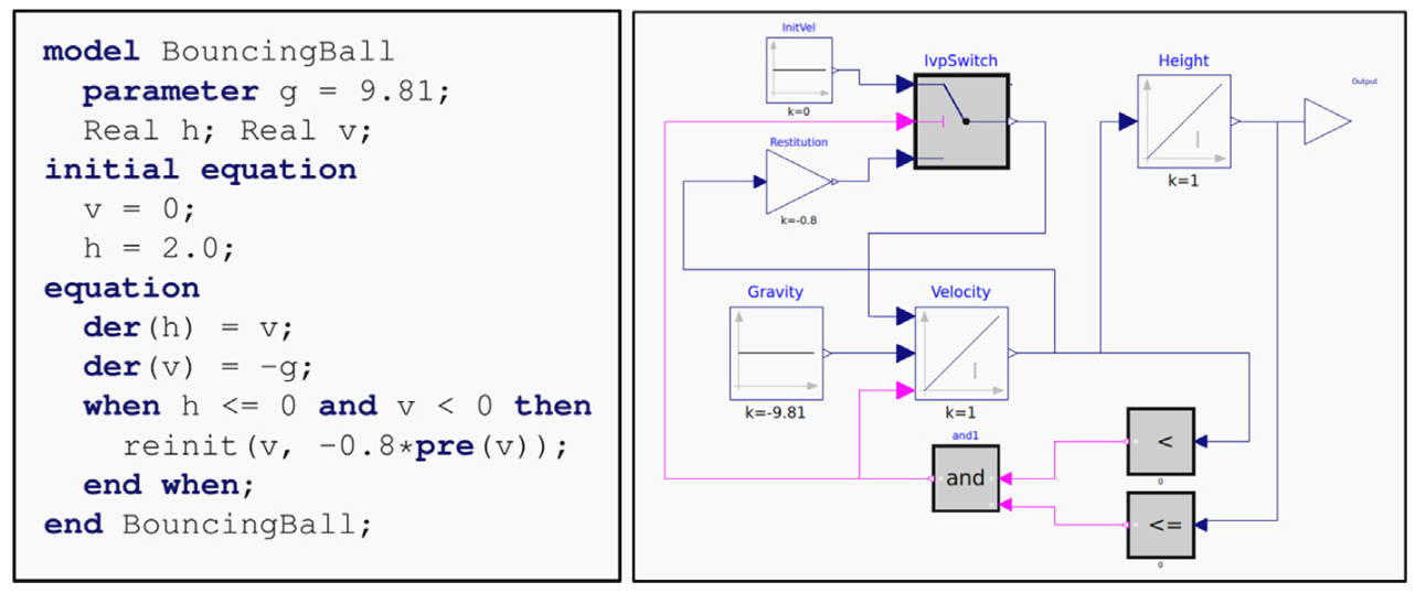
Figure 3.2 OpenModelica model of a bouncing ball in equation and graphical form.
4.3.2 VDM-RT and Overture
- VDM-RT is the real-time dialect of the Vienna Development Method, a wellestablished formal method for DE modelling.
- VDM models describe systems and components in terms of their state and how that state changes in response to inputs, such as test data or values from other models during co-simulation.
- Overture is an open-source tool for writing and analysing VDM models.
- It provides syntax and type checking, analysis techniques such as combinatorial testing, and simulation of an executable subset of VDM.
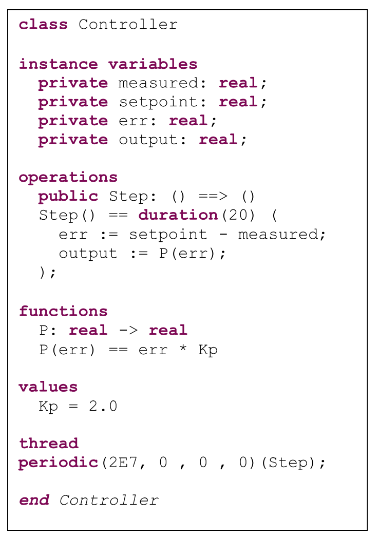
Figure 3.3 Simple controller class in VDM-RT.
5. AN EXAMPLE OF CO- MODELLING: RAILWAY INTERLOCKING SYSTEM
5.1 Premise
- In railway signalling, an interlocking is an arrangement of signal apparatus that prevents conflicting movements through an arrangement of tracks such as junctions or crossings.
- Usually interlocking is in charge of a complete line, computing the status of actuators (switches, signals) based on signalling safety rules that are encoded as so-called ‘binary equations’.
- Overall such a system is in charge of a complete line, where it computes the status of actuators based on signalling safety rules that are encoded as ‘Boolean equations’
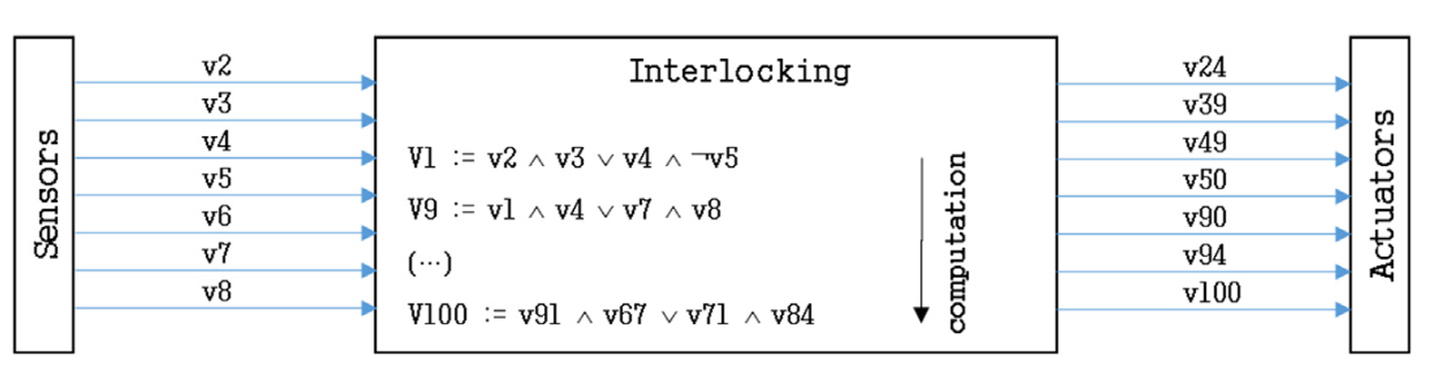
Figure 3.4 Boolean equations lead a signalling system.
5.2 THE CHALLENGES OF INTERLOCKING
- A single central interlocking can deal with a complete line, all decisions being made globally.
- However, the distance between devices distributed along the tracks and the interlocking system may lead to significant delays in updating the status of the devices.
- Moreover, this architecture, well dimensioned for metro lines, is often overkill for simpler infrastructures like tramway lines.
- So there is room for a distributed interlocking solution in which a line is divided into overlapping interlocked zones, each controlled by an interlocking system.
- Distribution implies several engineering challenges.
- An ‘optimal distribution’ (i.e., the decomposition of the line into overlapping areas such as to minimise delays, availability and costs) requires smart exploration of the design space (decomposition is directly linked with railway signalling rules).
- It also implies that one has to define what information is to be exchanged between interlocking computers and how many equations have to run on any of them (20,000 equations maximum, for example).
5.3 ACCURATE TRAIN MOVEMENT SIMULATION AND CHALLENGES
- In order to have a realistic overview of traffic and to deal with safety, train movements along the track map have to be simulated in a realistic way.
- The greater the fidelity of movement simulation, the more one can ensure that an interlocking system is efficient but safe.
- Usually, a train receives or considers a Movement Authority Limit (MAL): a stop point that it must never overshoot.
- Such an MAL is updated in real time by interlocking mechanisms and communication facilities.
- For an automated train, automatic train operation (ATO) computes the best movement for reaching a stop at the MAL.
 Figure 3.5 Usual safe braking model. ATO, automatic train operation; ATP, automatic train protection.
5.4 COLLABORATIVE MODEL-BASED DESIGN OF DISTRIBUTED INTERLOCKING
- A distributed approach might help to reduce the global length of the connections and therefore the cost and the risk of failure.
- Fig. 3.6 shows a possible division into five zones (ZQ2, ZQ3, ZP, ZV1 and ZV2), each ruled by an interlocking module.
- Such modules would require less computational power than a global interlocking as fewer local devices have to be handled; local decisions that only involve local devices could be taken more rapidly and potentially yield faster train transfers.
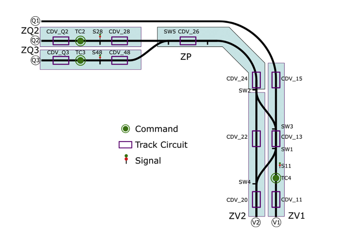
Figure 3.6 Distribution of the interlocking system over the track map.
5.5 MULTIDISCIPLINARY CO-MODELLING
5.5.1 Architecture of the co-model
- There are many approaches to co-modelling and the choice of which to use depends on the expertise of the organisation(s) involved in the modelling and the perceived challenges of the project.
- Here we assume a scenario with two teams, one experts in DE modelling, the other with skills in CT modelling and both sharing the goal of constructing a competent model of an existing rail system.
- In this case the engineers begin by constructing an architecture of the co-model they intend to produce with the purpose of defining the interfaces each model will eventually provide and expect.
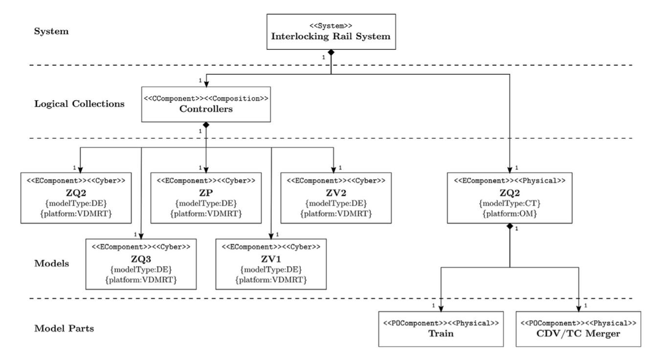
Figure 3.7 Architectural structure for case study rail system.
- The CT model exists in two flavours.
- The first version simply models a train following a precalculated route; it can start and stop depending on authorisation signals and can trigger interlocking sensors, command or track circuit.
- It is decomposed as a driver and an engine; the driver is reading the signal and provides an acceleration (positive or negative), and the engine integrates this acceleration to provide a position, setting the sensors.
- This version is developed using OpenModelica block representation.
- A more sophisticated CT model reproduces more accurately the behaviour of the train.
- In this version the driver still reads the signals and provides a set point speed.
- Then the engine uses its acceleration and braking capability to try to reach the set point speed.
- The calculation of the position takes account of the track chaining and switch positions.
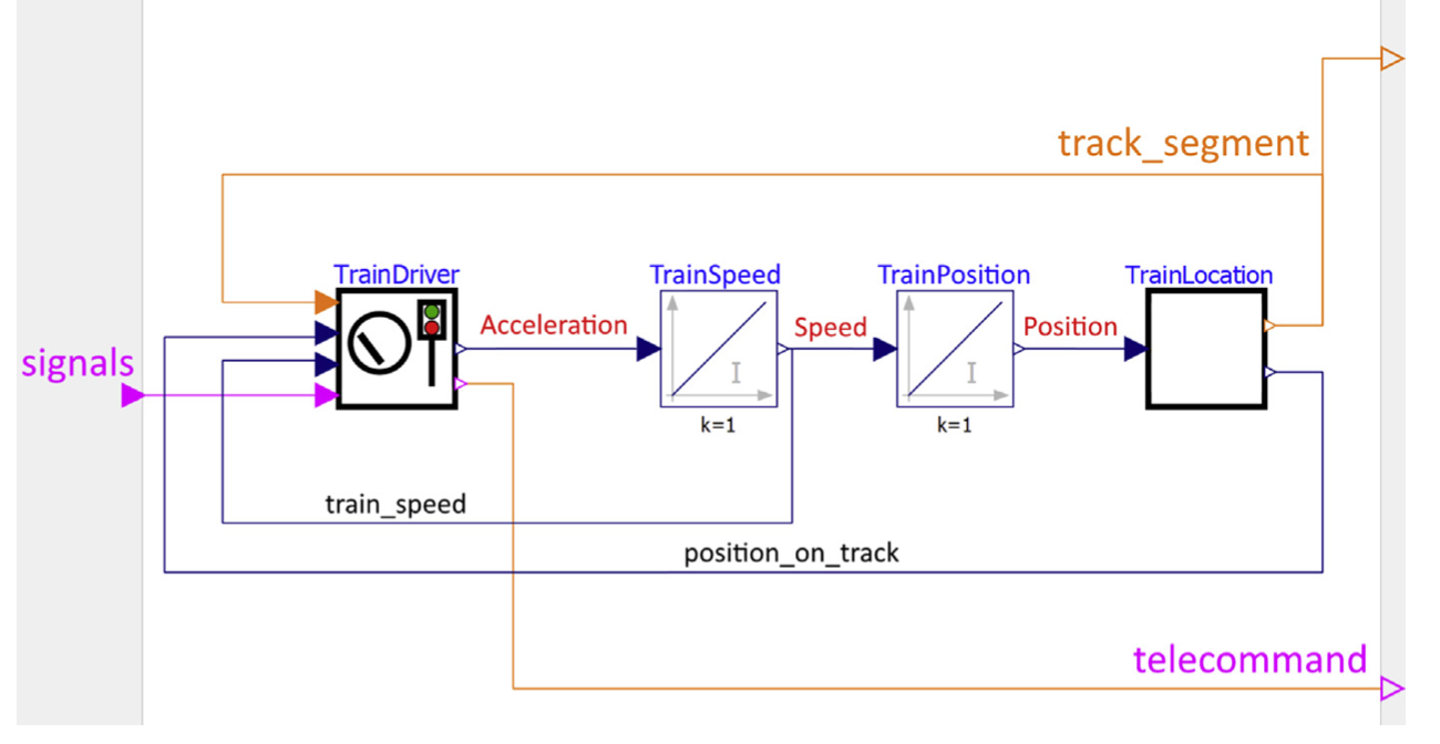
Figure 3.8 Simple continuous-time model of a train.
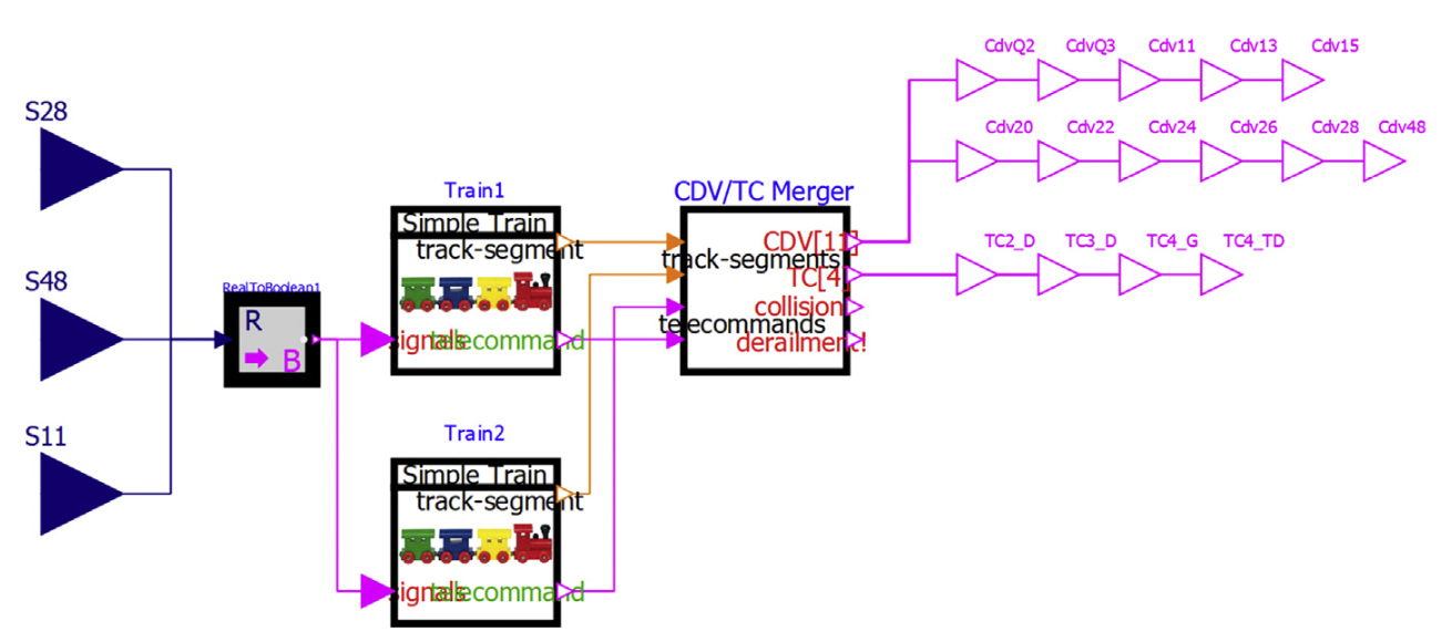
Figure 3.9 Continuous-time model of train behaviour in OpenModelica
5.5.3 DISCRETE- EVENT MODEL OF THE DECENTRALISED CONTROLLER
- The physical components of the interlock CPS have been addressed, and so it remains to model the cyber controller and this is best done in the DE environment.
- The controller has previously been decomposed into five distributed zonal controllers, and so the challenge for the DE modeller is to model the behaviour of each of those zones.
- Here the behaviour really means the setting of the track signals in response to routes requested by the trains along with their sensed positions.
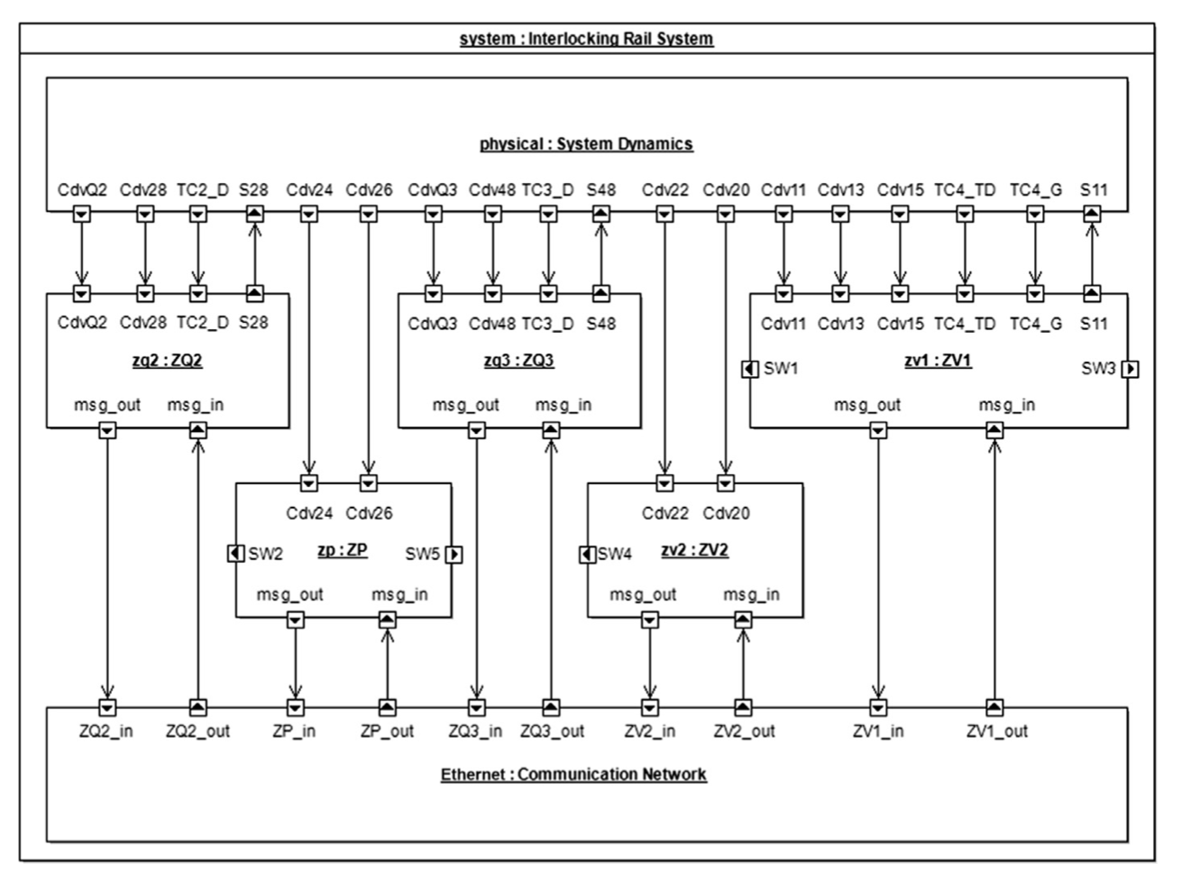
Figure 3.13 The connection diagram showing the two- model Functional Mock-up Units and their port connections.
5.8 HARDWARE- IN-THE-LOOP SIMULATION
- It is possible to perform HiL simulations, where selected component that were previously modelled are replaced with suitably instrumented hardware.
- In the case of the train interlock example, HiL simulations can be performed where the DE controller FMUs, along with the Ethernet FMU, may be replaced with the controller hardware running code generated from DE models.
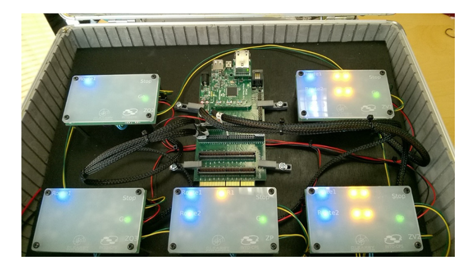
Figure 3.19 A hardware-in-the-loop simulation of the train interlock system, where the controller and Ethernet Functional Mock-up Units are replaced with generated code running on actual hardware. The train dynamics are still represented by the continuous-time model as a simulation.